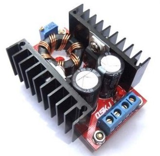
In a recent project, I needed a boost converter to step up 5V to about 8V at a few amps. A few different Chinese-made boost converter modules are available from various sources: I’ve seen them on eBay and Amazon. One very common one is known as the ‘150W Boost Converter’. I believe it’s intended for charging laptops from car batteries. It’s specified to take an input of 10-32V and output 12-35V, which isn’t quite what I was looking for, but the price was right so I thought I’d take a chance. This is what I found.
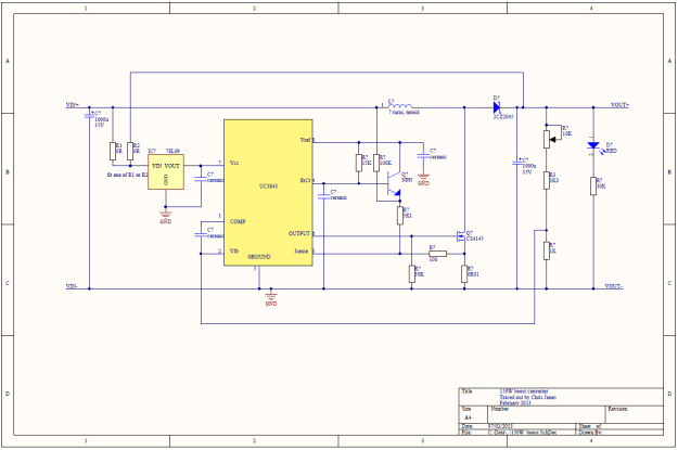
I had a good look at the circuit board. It’s based on the UC3843 chip, which is a pretty old device (I think it dates back to 1984) and is often found in PC power supplies. However, its age and ubiquity means that documentation on it is readily available. I traced out the circuit, so here’s the schematic diagram:
You can also have it as a PDF file: 150W_ boost.
It’s a pretty straightforward boost converter topology with a MOSFET switching transistor and a variable resistor in the feedback loop to set the output voltage. There is no over-current, over-voltage or reverse polarity protection at all, and the chip isn’t designed for low power consumption so this module wouldn’t be suitable where very low standby power is a requirement. There are a couple of interesting features, though.
The circuit includes an arrangement with an NPN transistor which feeds some bias to the current sense feedback loop. According to the UC3843 datasheet, this improves the stability of the converter at duty cycles higher than 50%.
The control supply for the UC3843 is derived from a 9V regulator, so it’s independent of the input or output voltage. This is convenient.
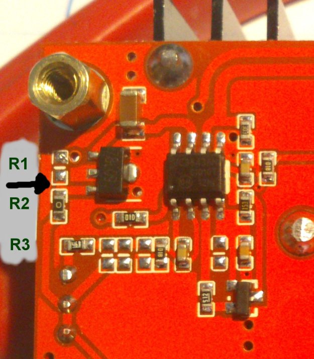
The UC3843 is designed to operate from fairly high supply voltages, and won’t start up until its supply voltage reaches 8.4V. That was a bit of a problem for my application, where the input voltage was only 5V. However, there’s nothing to say that the chip power supply has to be the same as the power input. In fact, the module already has a handy 9V regulator which feeds the control chip. Looking at the circuit diagram, there are even a pair of resistors (I’ve labelled them R1 and R2) which select whether that regulator is fed from the input or the output. As supplied, R2 was fitted, so the control chip was fed from the output. Here’s a closeup of the relevant part of the board showing R1 and R2.
My application happened to have a low-current 12V supply available, which would be perfect for powering the UC3843. I simply removed R2 and connected my 12V supply to the point where the black arrow is in the photograph. The boost converter now worked perfectly with a 5V input.
I also had to modify it a little to be able to reduce the output voltage below about 11V. R3, labelled in the photo, is part of the feedback network. I simply removed it and replaced it with a piece of wire. Now the output voltage was variable down to 5V, and I was able to set it to the 8V I wanted.
The module seemed very comfortable delivering 3.3A at around 8V, and drew about 5A from the the 5V input. The heatsinks only got slightly warm.
Unfortunately, the power supply I wanted to run the converter and its load from didn’t like starting up with it all connected. This is quite often a problem with boost converters, since the inrush current at startup can be very large as the controller tries to bring the output up to voltage as quickly as possible. I solved this by adding a soft-start circuit to the module. More on that later.


Do you think it would be possible to parallel two of these for 300W of power? Thanks.
It might work, but you couldn’t be sure of getting the load balanced between the two converters. I wouldn’t rely on getting double the output, that’s for sure. A slightly more reliable way of paralleling them might be to remove the controller chip from one of them and just connect the gates of the MOSFETs on each converter together, so they switch at the same time. Then at least you won’t have two feedback loops fighting each other. The UC3843 and its brethren are not really designed to be paralleled, though.
I just did this with 4 of them. It dumps 400 watts into my dummy load and iys power output is balanced between all of them. Just remember to tie the input and output of the boards together as well or nothing will happen.
That’s good to hear. It seems the current-mode operation of the UC3843 leads to nice load sharing, which is good news!
hello, you talked about soft-start circuit to the module.
where can i see more about it?
thank you.
I haven’t documented it yet! Sorry about that. It’ll be along some time soon.
Hello, i have nearly same module: it is only 120W but it have boost up to 60V. I see diference only in toroidal coil… So I think, if I use your schematic but i replace toroidal inductor by another one with lower max. current, and higher inductance, i will reach effect of higher voltage on output… Am I right?
thank you for the schematic… there ist that module http://dx.com/p/120w-dc-dc-10-32v-to-35-60v-boost-converter-charger-module-red-156701#.UuWz7hBjWHs
That module looks very similar. To get a higher output voltage from the ‘standard’ 150W module, you won’t need to change the inductor, since this is a flyback-type converter and the properties of the inductor are defined mostly by the input voltage, switching frequency and output power required. You will, however, need to make sure that the switching transistors and output capacitors are rated for the full output voltage, and modify the feedback resistor network so that the output regulates at the new, higher voltage. Increase the value of R3 (try 10k) or reduce the value of the 1K resistor below R3 (try 470R). I hope this helps you.
Chris
Hi,
Thanks for this write up. I’m trying to use this same converter to run a 100W LED. I will run from a 12V lithium battery, to the converter, then the LED runs on 35Volts.
Will this booster be suitable, or will the LED draw too much current? I’m not sure,
Thanks,
I think the converter should be able to handle the load, though it’ll probably get quite hot. I would be more worried about limiting the current to the LED. LEDs can’t usefully be driven from constant-voltage sources like this boost converter: they have a negative temperature coefficient of resistance, so the current will increase rapidly as the LED warms up. You’ll need a constant-current supply. This boost converter could be turned into one but you’ll need a current sense resistor and a an amplifier to boost the voltage across the current sense resistor to the feedback voltage that the control chip needs.
dear sir , i am doing my project with this converter so could u explain me the working principle of this model
Sure, no problem.
http://lmgtfy.com/?q=boost+converter
Hope that helps!
Chris
Deaar Martin,
thanks for your write-up, but the circuit-schematic is wrong. The 100k-resistor goes straigt to pin 3. We actually modified this circuit to run as a CC/CV step-up-boster with just 3 additional parts. The original circuit is somewhat crude regarding the compensation-capacitor and the 100k.
If you want to join us, i may send your our ltspice-project.
http://www.360customs.de/2014/05/103050100w-led-applikation-treiber/
google-translation is available on site.
Regards,
Christian
Christian, thanks for the comment and the correction. I’ll check my board next time I look at it and confirm where the 100k resistor goes.
Hi Martin/Chris,
thanks for the reply. I measured different loads connected to this converter, and can say, that more than 60W isn’t possible without heavy cooling. The best way to increase performance is to change the winding on the inductor to ~twice the winding-count with high-frequency-braid (wire).
Regards,
Christian
Dear All,
do you have any update around the 100k connection?
Thanks in advance!
Powermos
Not yet – the board is still on the workbench but I keep forgetting to check.
This one is 100% valid:

i have the same circuit, i connected input supply incorrectly and it blew up something. i am trying to fix it and currently it is only giving 12v as output and not anything above input. i have replaced 75nf75 but no use, i was able to figure out the output of 75l09 as 8 v and not 9v. i tried supplying 12v to uc3843 but the output is still 12v. any thoughts.
I think your UC3843 has probably died. Fit a new one!
I have this unit and wanted to use a 10kpot with a knob in place of the trim pot. The solder they use required a very high temp (my desoldering iron wouldnt melt it. Soldering iron did) in the process I melted the smd you label as r3. What will happen if I lay a wire across it (or use the wire im running to the pot actually)?
You’ll be fine just bridging R3. All it does is limit the minimum output voltage.
Thank you for a great article.
Do not have more information about soft start?
Thank you.
Thank you for your interest in the article. I’ve successfully implemented the soft start but not yet documented it. I hope to do it soon.
Chris
Hi and thanks for this article. I just received 3 of these same units that I now realised I ordered by mistake. I needed constant current to drive LEDs. Is there an easy hack to ad cc to this board?
Yes, but it wouldn’t be especially efficient. Calculate a current sense resistor which will drop 1.2V at your desired current, and connect it between the negative side of the load and ground. Connect the top end of the current sense resistor to the feedback pin on the UC3843, and you’ll have constant-current operation. Beware that if your LEDs have a forward voltage of less than the input supply voltage, the boost converter won’t be able to limit the current to them. And if your LEDs come disconnected, there’s nothing to limit the rise in the boost converter’s output voltage. That’s another refinement!
That’s why you or’ing both to the regulation loop (via diode) to have voltage and current limit.
If you’d be prepped to desolder the current UC3xxx chip, TI offer a version that offers softstart with the addition of 4 components, take a look at the UIC38C41. Great article though!
Hi Chris. I found this page googling information for this boost converter.
I accidentally reversed the input voltage (rookie mistake, I know). The input I was using was a 12v battery.
Which component would you guess was the first one to blow? It was only connected for 5 seconds but there was a bit of smoke.
Any hints you can give me in where to start checking will be appreciated. I don’t live in the US so buying a new one is my last option.
Thanks in advance.
I suspect the MOSFET is going to take the worst hit – it will conduct lots of current when the input voltage is reversed, and by doing so will probably protect the controller chip and all the other bits. I’d check that first. You’ll probably find it’s short-circuit now.
Ya, also check the shunt resistor and input caps, They might get damaged and cause more leakage now. If they get warm now, something is wrong with them.
Beside this, changing the inductor for a “better” one greatly improves performance. With a Coilcraft VER2923 it easily does 140W at 12->36V without running hot. Sure, the inductor is more expensive than the whole converter, but if you need a performance kick, go for it.
Thanks to both for your help. I think the MOSFET is indeed short-circuit because upon visual inspection one of the terminals in the 10mOhm resistor is lifted up. The PCB doesn’t looks burned in any way. I haven’t had time to remove and check any components yet.
Thanks for the coil recommendation. I wonder if can salvage one from an old PC power supply.
Regards,
Diego
Thanks for all your help. The only component that needed to be replaced was the 7809 voltage regulator. I bypassed it to an external power supply and everything seems to be working. I have to do some tests under load to see if everything is normal.
This definitely is not the circuit you want for driving a led. It lacks a current limiter and has a high output voltage peak on every start up that will shorten the life of the led.
Regards,
Diego
Then add a current limiter some some arts from the bin. You may have a look on my website, there’s a tutorial.
Thanks Christian, I did checked the website but those modifications are beyond my skills when it comes to soldering on the board.
I ended up replacing the SMD 7809 with the TO92 version, and it was nerve wreaking jajaja
The output voltage is not Adjustable it is equal to the input. how can I solve it? please help me. Thank you.
It sounds like the boost converter is simply not running. It may have been damaged by a wrong connection in the past. It’s likely that either the controller chip or the switching MOSFET is damaged. You could use a multimeter to check the conditions around the controller chip and see if it’s providing gate drive pulses to the MOSFET. Check the data sheet for the controller chip to see how it should be working.
Pingback: Super Breakout to JAMMA, Part 1: Power Supply | martinjonestechnology
For your reference:
The Parts use in each version—–.
FET Diode Inductor Output Capacitor
90V Output Version: SUP85N10-10 Vds=100V STPS20S100 Vr=100V 50uH 330uF 100WV
30V Output Version: STP80NF70 Vds=68V STPS20L45CT Vr=45V 5uH 1000uF 35WV
250V (90V) Output Modefication: 2SK3234 Vds=400V KCF16A60 Vr=600V 220uH (LHL13NB221K) 100uF 160WV
That’s useful information, thank you.
i tried to make a project with schematic like this but still no output voltage constraint still same with input. I need help
The output voltage will be the same as the input if the control chip is mis-wired or faulty. Check the feedback voltage: if it’s greater than 1.2V, the chip won’t try to boost the output. Is the MOSFET connected correctly? Do you have a scope to look at waveforms?
I have a problem there is a resistance on mine burned all he is but 0.01 ohm, on the picture that Christian has placed is the resistance number 8 but because he is such a low resistance, it is necessary to him with a new to replace or can I simply replace it with a piece of wire or solder.
can you help me?
That resistor is a current sense resistor that the control chip uses to monitor the current in the inductor. A piece of wire won’t do – it will have too low a resistance. Without the correct resistor, the circuit won’t work properly and will probably damage itself. If the resistor has burned up, the MOSFET is almost certainly short-circuit as well (check with a multimeter on the ohms or diode test range) so you’ll need to replace both components.
Hi!
Very informative writeup. I just ordered a pair of these circuits — but then I realised I need a split ±25V supply. Is there any way to run one of them in inverting mode?
It’s possible to modify a boost converter to create a negative output, but not always easy. One way is to rewire it as a Ćuk converter (https://en.wikipedia.org/wiki/%C4%86uk_converter) which has a similar topology, but needs another capacitor and inductor. However, the voltage feedback ends up being the wrong way round, so you’d have to deal with that using a transistor or op-amp inverter. If you only need a small current from your negative rail, you can add the Ćuk converter components to just one boost converter and have it do both jobs, like in my Super Breakout JAMMA conversion (https://martin-jones.com/2016/09/17/super-breakout-to-jamma-part-1-power-supply/). Otherwise you’re better off starting with a buck converter, which you can use directly if you are prepared to move ground to your negative rail, or modify into a buck-boost converter.
Thanks for the quick reply! I’ll need it to drive a speaker so I doubt the negative rail needs a small current… Thanks though 🙂
I’m powering this from a pair of 12V lithium batteries if that helps.
Perhaps I could connect the batteries in series, then connect the inputs of the first one to the boost converter and adjust it to give 36V (the model I have is 12-46V)? Would that give me ±24V with ground being the cathode of the first battery (which can sink or source current)?
Since you have two batteries, why not connect each of them to one boost converter, giving you two independent 24V supplies, and connect those two in series to give you your +/-24V? The batteries remain disconnected from each other.
Hmm… I’ve thought of that but forums suggest that the boost circuit at ground won’t be able to sink current 😅
Hey it works well! Now my issue is, I need to make this an adjustable split supply (16v to 26v). Tried using a dual potentiometer but there’s some DC offset of about 0.1v. Any way to eliminate the DC offset?