A couple of weeks ago, my wife and I wanted to watch a movie. I went to put the DVD in the player, and was disappointed to find that the machine was dark and didn’t respond to any of its buttons. It was broken.

It’s hard to say that a DVD player is really worth fixing. This one, a Denon DVD-1720, is about 7 years old, and wasn’t expensive when it was new. However, I was curious to know why it had stopped working, and that alone was reason enough to delve inside.
Considering its low cost (I think it cost about £100 when new) it was very neatly constructed. Removing a few screws allows the top to come off (careful of sharp edges) and the plastic front panel just unclips with a bit of gentle persuasion, revealing the guts.

Before we go any further, I have to insert a health warning. Dealing with DVD player power supplies has health risks. There are dangerous voltages present inside. If you don’t have the right equipment or don’t know what you’re doing, you can get a nasty surprise, a terminally broken DVD player, a serious injury or be electrocuted. None of those are fun, especially the one which results in death.
Almost all the electronics are on one big motherboard, apart from a few buttons and lights at the front and the fiddly digital stuff to do with the actual DVD reading, which sits on the green board on pillars in the middle. Undoing the screws from the green board, a few on the motherboard, all the ones on the back of the machine, and unplugging three connectors, makes it possible to wiggle the board free. It’s a bit of a squeeze and the board is fragile, so don’t blame me if you break it.

The power supply is at the rear right corner. Denon have kindly marked in white the area with dangerous voltages in it.

There’s not much to it. It’s clearly a switch-mode flyback converter. The transformer is much too small to be an ordinary mains transformer, and there are no inductors on the secondary side. I did the obvious checks – the fuse wasn’t blown, and the three big pale blue safety resistors measured OK. All the diodes dioded too. Time to put my reverse engineering hat on and dig deeper.
The PCB is nicely marked with the component identifiers on both sides:
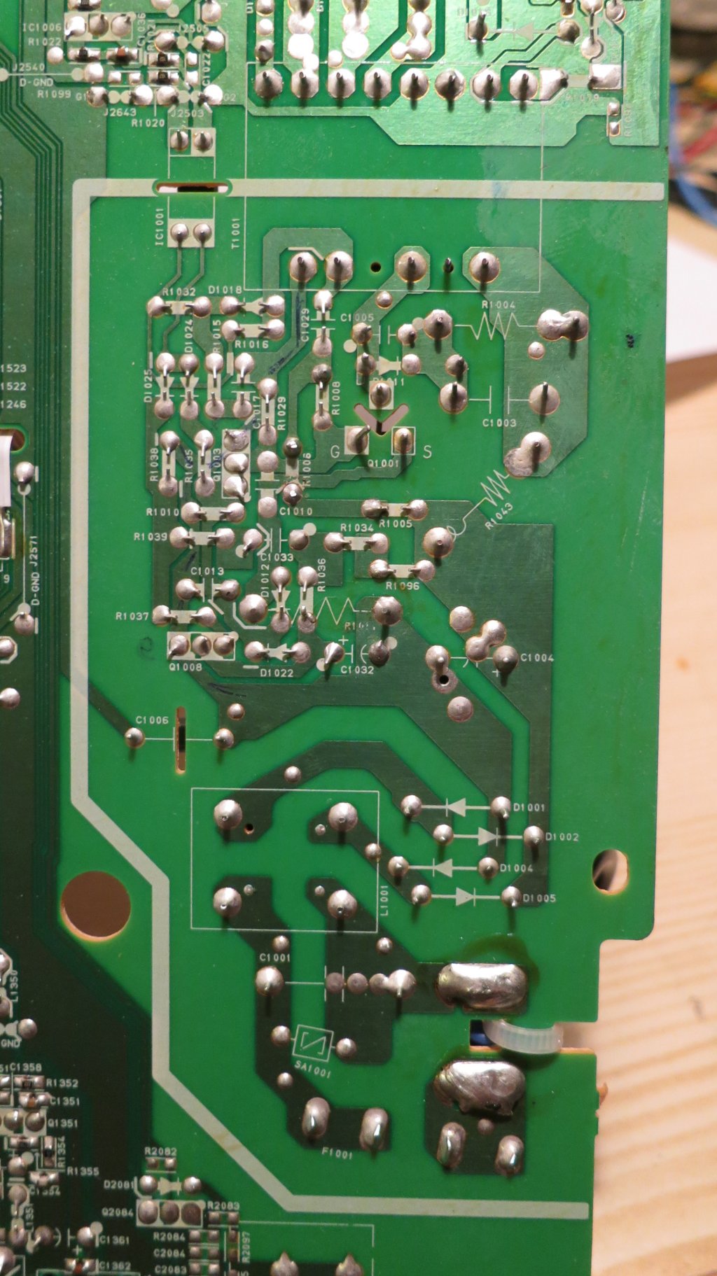
so it wasn’t too hard to draw out the circuit diagram.

It’s a pretty elegant design, using only three transistors. The circuit appears to be a blocking oscillator centred around Q1001 and the transformer. At startup, Q1001 is allowed to conduct, and current starts to flow in the transformer primary. At a certain current, the transformer’s core will saturate so the current can’t increase any more. The voltage induced by the changing core flux in the feedback winding at the bottom of the transformer will suddenly drop, creating a pulse which, fed via C1029 to the gate of Q1001, switches it off. At that point the energy stored in the transformer core has to go somewhere, and it finds its way out through the secondary rectifiers into the outputs. The basic scheme is very similar to the Joule Thief, a simple blocking oscillator for driving LEDs from batteries.
The two transistors Q1003 and Q1008 seem to be involved in regulating the supply. Q1003 can cut off the gate drive to Q1001 in response to three things: the current in R1001 getting too high, the optocoupler IC1001 conducting too much (which indicates that the output voltage is too high) or Q1008 stopping conducting. The latter seems to be a way of shutting down the supply if its output voltages get low, or it might be a cunning standby mechanism involving some more stuff on the secondary side which I haven’t investigated. C1032 seems to be there to make sure that the power supply starts up.
I powered the bare motherboard from an isolating transformer (don’t try this at home, folks, unless you know what one of those is and how to use it) and measured some things. There was precisely no activity going on at all, apart from 300V on the reservoir capacitor C1004 and Q1001’s drain, as expected. I first laid the blame on the little electrolytic C1032, since they’re the most unreliable components in any modern electronics, but tacking another 10uF across it didn’t help. Holding my breath and briefly shorting C1032 didn’t bring anything to life, either.
Then I measured some of the DC conditions. Everything around Q1008 was OK, with R1096 and R1034 merrily feeding electrons into Q1003’s base and keeping Q1001 switched off. High-value resistors are the next most suspicious components in a circuit like this, especially when they’re teeny-tiny ones. I checked around the 1.8 megohm R1005 and R1006 which pull up Q1001’s gate. Clearly it couldn’t work without them. Lo and behold, my 10 megohm input meter showed 250V at the junction of R1005 and R1006. That can’t be right – the voltage should be more like 150V, since the resistors are the same value and basically connected straight across the 300V supply. I pulled R1006 out of its hiding place and measured it – it was open-circuit. Gotcha!
Soldering in a replacement 1.8 megohm resistor for R1006 brought the whole thing back to life. The secondaries seemed to have sensible voltages on them (3.3V and 12V at a glance) so I reassembled it far enough to test. It lit up, accepted a disk and played it. Success!
It’s a credit to Denon’s neat design that there were no screws left over when I put it back together. The whole machine is now back in action for the sake of a 2p resistor.

Pingback: Repairing a PC power supply | martinjonestechnology
01/28/2016 Hi-> Had a blown fuse in a Denon DVD-2500. Replaced it and it blew again. Googled searched & read your details. Am not an electronic tech. With magnifying glass, located a grey R 1002 on the power board that was cracked with very, very small silver drops on each side of cracks. Thx for the lead. May try to solder in a replacement. Suggestions what to use (resistor type)? Something I can pickup at Radio Shack or Fry’s Electronics here in the USA? Thx, Bruce in Phoenix, AZ
I don’t know anything about the DVD-2500, so I can’t say what type of resistor R1002 should be. To replace it you’ll need to know what value it is, and what power rating. If it’s the same tiny size as the ones in my DVD-1720 then it’s rated at 1/8W. If it’s a different colour to the others, or has a matt surface finish, it may be a special fusible safety resistor. Take the original to Radio Shack and see if they can match it.
However, if the machine is blowing fuses, replacing a resistor almost certainly won’t fix it. The first thing I’d check would be the input rectifier diodes (D1001-D1005 in my diagram) and then the main switching transistor (Q1001 in my diagram).
On a second look it is a D1001 input rectifier diodes that cracked. Again many thx! Will let you know outcome.
Hi-> (Sent you this note via email with photos.)
I’ve had zero luck trying to find the component. In the attached picture, one can clearly see the crack and material leaking out the sides of the gray D1001.
Any suggestions on where and how to describe the item that might get results? When I use the terms Input Rectifier Diode (D1001) both in
Google searches and verbally to electronics components shops (e.g. Radio Shack), they find nothing. They all seem to need the component
specific electronic characteristics to match it. Appreciate your thoughts. My approach to this, based on finding your article is to replace the one component
and if it works great; if not then into the trash.
Thx, Bruce
For D1001-D1004, the input rectifier diodes, I’d replace them with 1N4007. It’s a very common part and should be available from most suppliers, probably even Radio Shack, or cheaply on eBay. Good luck!