Monthly Archives: February 2018

RIAA phono preamp for Tascam M-1B Line Mixer

In the workshop I have a couple of these Tascam M-1B line mixers. They’re a very useful box: they have eight inputs, each with a level control and pan pot, which are mixed together and fed into a master volume control. There’s also a pair of headphone outputs with their own volume control driven by a headphone amplifier with enough voltage swing to drive 600 ohm headphones properly. Into the mixer I typically feed the sound output of my PC, other audio sources such as a cassette player (yes!), and a spare cable lying around on the workbench ready to connect to whatever I’m working on, or my phone. The output is connected to the workshop speakers. With this setup I can hear all the sources at once without fiddling around, switching anything or unplugging anything.

IMG_0608.jpg

Tascam M-1B Line Mixer

The workshop I set up a couple of years ago turned out to have space for a new audio source: a turntable. Great! I can listen to vinyl (not ‘vinyls’, please). I had a spare turntable on the shelf, so I put it in place. The trouble is, the turntable has a magnetic cartridge which can’t be connected straight to the line inputs on my trusty mixer. It needed amplification and RIAA equalisation. I could have just gone and bought an off-the-shelf preamplifier, but where’s the fun in that? Looking at the back of the Tascam mixer, there’s a blanking plate which looks perfect for adding a preamplifier, neatly built in. No worries about trailing cables or yet another power supply to plug in. Now to find a suitable circuit.

IMG_0609.jpg

A quick web search pulled up an application note from National Semiconductor for their LM833 audio op-amp which shows a simple preamplifier circuit. It then goes on to describes the circuit’s deficiencies and how a two-stage design can improve on it, but I decided to stick with the simple version.

I didn’t have any LM833 op-amps in the spares box, but did have some NE5532s, which are not only an excellent audio op-amp but live two to a package. Finding the passive components in the spares box also proved to be a challenge. Getting the right component values is one thing, but finding two identical ones of each proved to be impossible. However, all was not lost, so I thought. The RIAA equalisation curve needs three time constants, of 75µs, 318µs and 3180µs. I found pairs of resistors and capacitors that gave the same time constants as R1C1 and R2C2 even if their values weren’t what the original design specified. Here’s a circuit diagram with my substitutions marked in red.

riaa-schematic-modded

I built up a small piece of matrix board and tried it out. It worked, but didn’t sound quite right: there was a noticeable lack of bass. I decided to check the frequency response. The application note shows a useful table of the RIAA response at various spot frequencies, so I had something to compare my results with. I used the ARTA STEPS program with a PC sound card to measure the frequency response of my circuit. It took a bit of fiddling with the levels to get good results, since the phono preamplifier has a lot of gain, but the result looked like this.

response-first-attempt

The curve looks convincingly like the RIAA curve, but it should be +17dB at 50Hz (relative to 1kHz). In fact it’s more like +13dB in my version, so I’ve lost 4dB of bass. At the other end of the spectrum it’s more accurate: at 20kHz it’s at almost exactly -20dB as it should be. (Note, when taking readings from the plot, that the level at 1kHz is about -3dB. It’s the relative levels that are important).

What I’d neglected in my component value calculations was that the relative values of the two RC networks are also important. The National Semiconductor application note actually goes on to explain more about this, but I hadn’t read any further than the circuit diagram. Rather than delving in to the maths and risking discovering that I needed more components I didn’t have, I started playing with the values I actually did have. Here’s a plot of the before-and-after empirical results.

response-first-and-second-attempt

The green curve is the modified version. The level at 50Hz is now +17dB relative to the level at 1kHz, as it should be. Below 50Hz there’s a bit of a rolloff, but that’s not something I’m worried about – my speakers don’t go down that low and it makes for a useful rumble filter. The modified circuit is shown here.

riaa-schematic-modded-v2

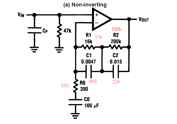
I had to change both RC networks to get a good result. The time constant of one of them (11k/6n8) is still 75µs, but the other (180k/22n) is more like 4000µs than 3180µs. I suspect it’s interacting with the time constant of R0C0 to give roughly the right result.

IMG_0616.jpg

It fits neatly in to the slot in the back panel of the mixer. The toggle switch connects the output of the preamplifier to inputs 1 and 2. Switching it off leaves those inputs available for normal line-level use if desired. There’s also an earth terminal.

IMG_0617.jpg

Time for some testing. What were the skies like when you were young?

IMG_0621.jpg

The Euroquadruped, or the solution to wall wart Tetris

Having relocated from the UK to Poland, the change in mains plugs has never quite been resolved. All the equipment that came from the UK has 13A plugs on it, and all the local sockets are the CEE 7/5 type. Then there are locally-acquired bits and pieces  which generally have two-pin Europlugs. No matter how many adapter cables and extension leads I make, or change the plug or socket on, there’s always something that doesn’t fit, or won’t reach the nearest compatible socket.

Of particular annoyance are various chargers and wall warts. They’re all bigger than a standard Europlug, and there’s no standard for which way the ‘lump’ of the charger will be attached, so connecting several of them in to a multi-socket extension lead doesn’t work well. Often one charger will obscure one or more sockets in such a way that all the things you need just won’t fit, or the whole assembly becomes so big and unwieldy that things start falling out under their own weight.

It is therefore with some relief that I announce the debut of the Euroquadraped: one 13A plug with short cables to four Europlug sockets. It reminded me of an octopus but only has four ‘legs’, hence the name.

IMG_20180211_221335.jpg

Getting all four cables in to the 13A plug was a bit fiddly, but choosing a roomy plug helped. The little Europlug sockets are neat. I’ve only seen them here in Poland. The finger ring to discourage pulling on the cable is a nice touch, and doubles as a cord grip internally. They even (finally) have safety shutters on the socket holes, roughly 60 years after shutters became standard on the British 13A socket…

The great advantage of this thing is that each socket is independent of the others and can find its own equilibrium with whatever electrical carbuncle is plugged in to it.

IMG_20180211_221527.jpg

It’s trivially simple, but it’s going to save a lot of frustration in the workshop.

Canon S100 Shutter Button Fix

This is my Canon S100 digital camera. After long, somewhat arduous service, the shutter button started playing up: it would focus but not take the photo. Eventually I got a mobile phone with a better camera and quietly forgot about the Canon. The S100 has been extensively frozen, boiled, soaked, rattled and trodden on, so I figured that the shutter button problem was just due to the abuse. It doesn’t owe me anything. However, it’s still useful for some things the phone camera won’t do: it fits a tripod, and has good long exposure and manual control facilities including a handy neutral density filter.

IMG_20180204_165606.jpg

Trying to use it to take some tricky oscilloscope photos the other day, the shutter button got really annoying. I searched on line for the problem and discovered that it’s quite common. That sounded like an interesting problem to me. Here’s my attempt at fixing it.

Before we start, don’t try this unless you’re used to dealing with annoyingly tiny things and have the tools to match: jeweller’s screwdrivers, tweezers, a very fine soldering iron and either amazing close-up vision or a good magnifier.

The camera comes apart surprisingly easily. There are six little black screws on the outside: two on each end and two on the bottom, close to the tripod mount. Take those screws out. The back comes off very easily – take care not to lose any of the buttons though.

IMG_20180204_165751.jpg

The front also comes off easily, though there’s a little FFC connector to the setting ring round the lens. Unplug it carefully. It doesn’t have a locking bar so the flex PCB just pushes in and out. There’s also a foam gasket round the lens and the plastic cover for the HDMI and USB sockets. They’ll fall on the floor.

IMG_20180204_165854.jpg

The shutter button and other controls are underneath the top cover. There are two more screws to remove: one on the front near the lens and one on one end. They’re different lengths so take note of where each came from. Before removing the top, there’s one more FFC to unplug. This one connects to the microphones. Again it has no locking bar so just pull gently. It’s the middle of the three FFCs in this photo.

IMG_20180204_170148.jpg

With the top cover off, the controls themselves are revealed. On the left here, the function selector rotary switch, then the shutter button and zoom switch, then the power button, and on the right the big square thing is the GPS antenna.

IMG_20180204_170233.jpg

If you put the battery back in, the camera actually works fine in this dismantled state, so it’s easy to try experiments. I prodded and poked the shutter button. Sometimes it worked, sometimes it didn’t. I doused the button with my favourite contact cleaner (DeoxIT D5) to no avail. I looked on the web for replacement buttons: “double action tactile switch” seemed to be the best thing to search for. There are lots out there which might fit, but they’d take a while to get hold of and would be really fiddly to solder, especially with the zoom switch so close by.

I wondered about a mechanical solution, extending the plastic rod from the outside shutter button that presses the switch to give it more poke, but sometimes the switch just refused to work no matter how hard I prodded it with a screwdriver, so that probably wasn’t worthwhile.

Given that it wasn’t worth spending a lot of time on what’s effectively a life-expired camera, an alternative engineering solution was called for. The first stage of the shutter button, the half-press to lock the focus and exposure, still works reliably. What if I just wired it in parallel with the shutter release contact? Then there would be no way to lock the exposure and focus, but at least the camera would take photos.

Some fiddly soldering with a fine iron bit and some polyurethane-insulated mod wire later, the two opposite corner contacts on the button are connected…

IMG_20180204_172823.jpg

…and the S100 lives again. It’s not a full fix, call it a workaround, hack or bodge, but it’s good enough for me to take pictures. Oh yes, and assembly, as somebody once said, is the reverse of disassembly.