Monthly Archives: January 2013

HP 16500A CPU board versions

As part of my quest to upgrade my HP 16500A logic analyser’s memory, I’ve found out more than I ever expected about the various versions of the 16500A CPU board. I’ve been fortunate to have the help of the good people of the [hp_agilent_equipment] Yahoo! group. My most recent stumbling block has been that installing ROM version 00.02 in my (early) 16500A stops the floppy disc drives working.

Glen Slick, from the above group, was kind enough to send me high-resolution scans of the two 16500A CPU boards he has. That makes three known versions, and here I’ll post pictures of them and attempt a description of the differences.

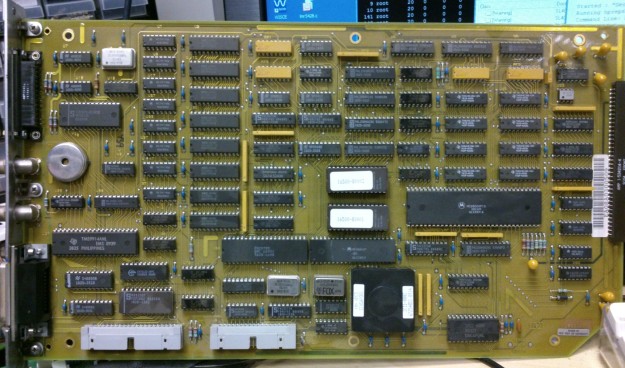
16500-66503 with 1MB RAM

DSC_0262

This is the board from my machine. It has 1MB RAM in 8 TMS44C256-12N DIL chips, and the floppy disc controller is a Standard Microsystems FDC9793. The ROMs contain software version 00.00. For completists, I have put images of the V00.00 16500A ROMs here.

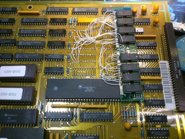
16500-66507 with 2.5MB RAM

16500-66507-FRONT

This is one of Glen’s boards. It has 2.5MB RAM fitted as 20 off TC514256AZ-10 1Mbit ZIP chips, and the floppy disc controller is a Zilog Z0765A (which seems to be compatible with the very common uPD765 as found in the original IBM PC). The ROMs contain software version 00.02. It also has three extra programmable devices with labels on them. The details of their encapsulation mouldings look very similar to PALs elsewhere on the board, but why don’t all the PALs have labels on them? The labelled ones are:

  • 16500-80006, U86, by the floppy drive connector at the bottom
  • 16500-80007, U104, top right
  • 16500-80008, no designator visible, next to the floppy controller IC

16500-66510 with 4MB RAM

16500-66510-FRONT

This is another of Glen’s boards. The part number (66510) seems to be on a sticker. The only noticeable difference, other than the RAM chip complement, from the 66507 board is that the chip top right is labelled 16500-80013. It has 4MB of RAM as 8 off TC514400AZ-80 4Mbit ZIP chips. The ROMs contain software version 00.02.

Using a 32.768kHz external crystal with Atmel XMEGA microcontroller RTC

I’ve just brought up a project using an Atmel XMEGA series microcontroller which uses an external 32.768kHz crystal to run its real time clock (RTC). I had some trouble getting it to work, but now I’ve found the recipe, thought I’d share it in case it’s useful to anyone.

DSC_0308

In principle, you’re supposed to enable the crystal oscillator and then wait until the XOSCRDY bit is set in the OSC.STATUS register, indicating that the oscillator has started up. My problem was that the oscillator seemed to be running, with a healthy-looking waveform at the XTAL1/TOSC1 pin, but the ready bit never got set.

DSC_0309

It turns out that the order of initialising the registers is important. You have to set XOSCCTRL first, to configure the oscillator, then enable it in CTRL, then wait for it to be ready. The code looks like this

OSC.XOSCCTRL= OSC_XOSCSEL_32KHz_gc;
OSC.CTRL|=OSC_XOSCEN_bm;
while(!(OSC.STATUS&OSC_XOSCRDY_bm));

That’s what worked for me. I’m using AVR Studio 6 and AVRGCC version 3.4.1.95.

Bubble Development Board V1.0

I’ve just got V1.0 of a development board for the ‘Bubble’ embedded ARM module ready for manufacture, and will hopefully have prototypes soon.

BubbleDevBoard1.0

It’s designed to make the Bubble board easy to work with, and brings out various useful connectors:

  • JTAG ports compatible with Xilinx (14-pin) and ARM (20-pin) dongle pinouts
  • Serial port for the console
  • USB host, for memory sticks, keyboards and whatever else
  • USB slave, for mass storage or USB networking
  • Micro SD card
  • HDMI for monitor connection
  • Ethernet
  • Stereo analogue audio in/out
  • Raspberry-Pi compatible expansion connector with I2C, SPI and GPIO

It’s all powered from a Micro USB connector which should take a standard mobile phone charger, and is designed to sit neatly in a low-cost plastic box for protection.

Everything except the Ethernet port is already supported by Linux on the Bubble board, though making the HDMI port work will involve some fiddling with the LCD output timings. The Ethernet port is based on the Wiznet W5100 chip, which is popular in the embedded community and is supported by recent Linux kernels.

Super Pacman repair log

I’ve just got an old Super Pacman arcade game running. Not the whole cabinet, you understand, which would be inconveniently large, but the circuit board from inside one, connected up to a monitor and joystick.It’s the lesser-known 1982 sequel to Pacman and Ms Pacman. It’s a fun game, with more complicated gameplay than the original: gates, keys, a speed-up button and a special powerup which makes you really big and able to go charging through everything. I could find hardly any repair information about Super Pacman on the internet, so I thought I’d paste my repair log here so people can see it.

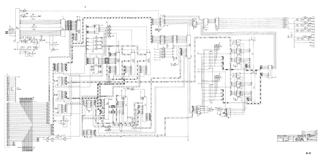
Firstly, as part of the process, I pasted together large high-resolution circuit diagrams by cutting and pasting from the available PDFs of the manual in which they’re sliced up into pages. The ones I’ve stuck together are more convenient to use when printed out on large sheets of paper or viewed on a big screen. I hope they’re useful.

super-pacman-cpu-hires

super-pacman-graphics-hires

Super Pacman repair log

1/1/2013

Connect up power and video. Occasional flashes of something on the screen but no sync. Main clock oscillator is running.

Lack of sync output seems to be due to unenthusiastic 74LS10 at 3A. Output at pin 12 is weak. Vertical sync input at pin 13 is OK but H sync input at pins 1 and 2 is very poor – barely leaving +5V but pulses are visible. Comes from a custom chip 2C. Hope it’s not knackered. Cut pins of LS10.
Output of custom recovers.

Replace 3A. Now we have a picture of random junk in blue and green which wriggles a bit when reset button is pressed.

Why does there appear to be no red in the picture? There’s activity on R video pin even though pin 1 of colour PROM 4C has snapped off. Maybe a blanking problem.

2/1/2013
RGB outputs are high during what should be blanking interval. Investigate inputs to PAL 4D. 6/7/8/9 are all stuck high. They come from 74LS298 4L, whose inputs looks pretty sensible but outputs are all stuck high. Remove it ready for replacement.

Blanking signal from 3A pin 6 ends up at PAL 4D pin 19 and seems to force its outputs to 01111. In this state, output of colour PROM 4C is 10101111. That’s definitely wrong according to the MAME ROM image. Should be 00000000.

Can’t buy or program PROMs easily so try substituting with a high-speed OTP PROM: Atmel 27C512. Physically large but cheap and easy to program, 45ns access time is OK. Wiring:

82S123 27C512
O1   1  O0  11
O2   2  O1  12
O3   3  O2  13
O4   4  O3  15
O5   5  O4  16
O6   6  O5  17
O7   7  O6  18
GND  8  GND 14, 1,2,3,4,5,21,22,23,24,25,26,27
O8   9  O7  19
A0  10  A0  10
A1  11  A1   9
A2  12  A2   8
A3  13  A3   7
A4  14  A4   6
nCE 15  nCE 20
VCC 16  VCC 28

Now colours are sensible. Maybe 4L (74LS298) isn’t faulty after all – It might just be that no sprites are displayed so there’s no activity.

IMG_3556

PROM at 4E is losing pin 1. Need to sort it out.

10/1/2013
Try and work out why game doesn’t run. Activity on data and address buses. EPROMs 1 and 2 (1B and 1C on CPU board) verify OK. When it stops, it’s resetting the watchdog continuously!

Sound CPU isn’t running cos its reset input (37) is low. Comes from latch 2M (74SL259). Pulling it high for a moment makes it stay high, oddly.

15/1/2013
Repair pin 1 of PROM 4E with Dremel and bit of wire. Screen of random characters looks more and more sensible: the word ‘CREDIT’, or bits of it, seem to be appearing in places.

Replace suspect 74LS298 at 4L now replacements have arrived. Makes no difference at all.

18/1/2013
Start examining buses and their buffers. Buffered address bus (from CPU board 2H, 1H, 1E) looks OK but buffered data bus has some bits hanging around near 0 where they should be pulled high. Disconnect the two boards and the fault is definitely on the video board. Could be any of 74LS245 1E, 1K, 1J, 1H. Remove them all. Replace them with secondhand chips. Board still doesn’t run but pattern on screen is somehow a bit different. RAM fault? Piggybacking RAMs doesn’t have any
effect.

19/1/2013
Chip at 2E (Namco 04xx) seems to be associated with addressing the RAMs. We have replacements on some Pole Position boards. Try swapping it and results are definitely different: instead of just random characters, there are now random sprites as well. Try two different 04xxs (0429 and 0436) from Pole Position and they both behave the same. Assume they’re OK then
and the original is faulty. Game still doesn’t run. Can’t see any dodgy logic levels on video board and piggybacking RAMs doesn’t help.

Still no interrupts happening. 74LS259 at 2M on CPU board is behaving oddly. It is being addressed but none of its outputs are changing, but if I pull any of them high for a moment they stay high.

When CPU crashes, it sits in an 8-cycle loop. Record what’s going on.

A EEEEEEE8
  11F111F0
  77F777F0
  BCF89AF0
D 2F0B8003
  0B070001

A15 11111111
A14 11111110
A13 11111110
A12 00100010
A11 00100010
A10 00100010
A9 00100010
A8 11111110
A7 00100010
A6 11111110
A5 11111110
A4 11111110
A3 11111110
A2 01100010
A1 10100110
A0 10101010
D7 01011000
D6 01000000
D5 11010001
D4 01010001
D3 01000000
D2 00010000
D1 01010000
D0 01010001
RnW 11111110

It’s in a tight loop at E178-E17F, which finishes by writing the value 0x31 to 0x8000. That’s the address which resets the watchdog.

Analysing the code in MAME, it seems that the first part is a RAM test which copies the ROM (from E000 onwards) into the RAM and reads it back, comparing it with the ROM. If it fails, it will try to put up the self-test screen indicating which RAM has failed, then go into the loop at E178. A value of 0x31 in A I think indicates that the tilemap RAM has failed, at 2E on the video board. So it seems that the first RAM test is failing and it’s trying to tell us about it, but access to the video RAM is so broken that we can’t see it. The CPU is actually running correctly.

Replace RAM 2E. Doesn’t make any difference, but if I remove buffer 1E the screen should clear with after the RAM test. It doesn’t, and behaves a bit randomly. Remove custom 00xx at 2D, which is the video address generator and thus has the ability to mess up video RAM addressing, and game appears to run! But tilemap is all the same character, not surprisingly because nothing’s generating video addresses. Pin 1 has dropped off 00xx. Temporarily connect it with scalpel and we have action. Repair pin 1 properly and game runs.

Try inserting coins by tickling edge connector with grounded wire. We can start a game and control Pacman. Pinout seems to be the same as Grobda but with player 1 and player 2 swapped over.

Wire up single player JAMMA adapter. Sound works! Pleasant surprise. Some sprites sometimes become white squares, but reseating customs on video board solves the problem.

Game fixed.

Img_3558

HP 16500A memory upgrade part 6

In part 5, upgrading the software on my 16500A’s CPU board to version 00.02 resulted in a self-test failure, which wasn’t fixed by downgrading back to 00.00. I’ve just had a look to see why that was happening.

The front panel is connected to the backplane by a 10-way connector. I traced out the pinout of the connector:

  1. +5V power
  2. +12V power
  3. +5V power
  4. +12V power
  5. Ground
  6. Data
  7. Ground
  8. Data
  9. Ground
  10. On/off switch, ground to switch system off

There was no activity at all on pins 6 and 8, the data pins, even during self-test. I traced them through to the CPU board via pins 59 and 60 of the CPU board’s backplane connector, and thence to U90 pins 18 and 19. This is an HP custom chip. There seemed to be activity on many of its pins, but nothing on those two. Poking around, I found that two of its pins are connected to a nearby ceramic resonator which clearly wasn’t resonating. Aha! Got it. One of the pins of the resonator had broken. I soldered it back together and now the self-tests pass!

But there’s a fly in the ointment. V00.02 software doesn’t seem to be able to access the floppy disc drives, simply reporting ‘No Disc’ for both of them even when they’ve got discs in.

Looking at the floppy disc connector with a scope, the ‘drive select’ pins are definitely active. It seems that the pinout of Sony 3.5″ floppy disc drives changed at some point. The details are here:

http://www.retrotechnology.com/herbs_stuff/drive.html#35new

Pin#  Signal (Old Sony)  Signal (New Sony)  Pin#  Signal (Old Sony)        Signal (New Sony)
1     Disc Change Reset   NC                2     Disc Change Indicator    NC
3     +5V                 Key               4     Density Bit              NC
5     +5V                 Ground            6     Drive Select             NC
7     +5V                 Ground            8     Index Pulse              Index
9     +5V                 Ground            10    Drive Select 0           NC
11    +5V                 Ground            12    Drive Select 1           Drive Select 1
13    Ground              Ground            14    Drive Select 2           NC
15    Ground              Ground            16    Motor On                 Motor On
17    Ground              Ground            18    Direction Select         Direction
19    Ground              Ground            20    Step                     Step
21    Ground              Ground            22    Write Data               Write Data
23    Ground              Ground            24    Write Gate               Write Gate
25    Ground              Ground            26    Track 0 Indicator        Track 00
27    Ground              Ground            28    Write Protect Indicator  Write Protect
29    +12V                Ground            30    Read Data                Read Data
31    +12V                Ground            32    Head Select              Head 1 Select
33    +12V                Ground            34    Ready                    Disc Change

It seems that the ‘disc change indicator’ has moved at some point in the history of Sony disc drives. Maybe the new software is expecting to see the ‘disc change’ indicator before it tries to switch the drive motors on? Grounding pin 34 doesn’t seem to make any difference. The disc controller is an FDC9793. Looking up the data sheet on it, it doesn’t have any means of indicating whether a disc is in or not. Without a schematic, it’s going to be very hard to figure out how the software determines it.

HP 16500A memory upgrade part 5


Following on from part 4, I’ve now tried a newer software version in the 16500A’s EPROMs. Finding a couple of good 27C256s with 200ns access time took a few minutes, but there were no problems with the programming. So, I put them in the CPU board, reinstalled it in the mainframe, and switched on:imageOh dear. That’s not good. Without HIL (which is the socket for mouse and keyboard on the front), front panel (which I assume is the spinner knob) or touchscreen, the machine isn’t a lot of use. Must be a compatibility problem with the new software version, I think to myself. Swap in the old ROMs – and the problem is still there. Check the wiring to the front panel, all looks good.

This is annoying. I wasn’t expecting new faults with the hardware. When I next get time to spend on it, I’ll do the obvious checks for bent pins and so on.


HP 16500A memory upgrade part 4

Having worked out the wiring for a 4MB SIMM to the 16500A CPU board in part 3, I got out the mod wire and soldered it all together.

DSC_0281

It all went together quite easily. The pins, even on the SIMM, are so much further apart than modern surface-mount components that I’m used to dealing with. Notice the red wire running along the row of chips on the SIMM: that’s nOE, where I had to lift pin 16 of each chip and wire them together because the original SIMM tracks grounded them. I also cut the track joining all the pin 3’s (nWE) of the chips together, half way along the SIMM, so that the upper four chips had a separate nWE from the lower four, again because that’s the way the CPU board expected them.

Having checked and double-checked the wiring, I plugged the board into the mainframe and switched on. Much to my amazement, I heard the sound of the floppy drives seeking almost immediately. It was running! Once the monitor had warmed up, I could see that the mainframe was booting absolutely normally. It passed all its self-tests. But, did it recognise the extra memory? With some trepidation I stabbed the screen to select test mode and looked at the bottom line of the display:

DSC_0284


Oh dear. Just 1MB then. Serves me right for trying to make a silk purse out of a sow’s ear. I suspect ROM version 00.00 (what kind of a version number is that?) doesn’t support more than this, since later 16500As had a different ROM version and more memory. Just for kicks, I popped in the test disk and tried the proper memory test:

DSC_0283


At least the new RAM works as well as the old stuff did, even if it isn’t any bigger. I haven’t broken it, but I haven’t improved it either. I also tried loading the 16550A module software, just in case it was somehow able to find the extra RAM even if the rest of the system didn’t know about it, but it still reported that there wasn’t enough space.

I think my next quest will be to find a copy of the later ROM and program a couple of EPROMs with it. A quick Google search for ‘16500A ROM’ reveals this site:

http://www.jammarcade.net/hp-16500a-logic-analyser/

with an image of the later ROMs. When I get a moment, I’ll program up a pair of 27C256As and see what happens…


Replacing Bipolar PROMs

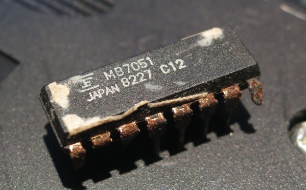
Back in the 1970s and 1980s, digital electronics made quite a lot of use of Bipolar PROM chips. They are a memory device, which can be programmed just once, holding only a few hundred or a few thousand bits of information. They were used for various tasks: address decoding, state machines, and video colour palettes, for example. They are very commonly seen in vintage arcade games and in other electronic devices too. Like any electronic component, they sometimes fail. They can be hard to replace, because they are no longer manufactured, and they are not supported by many low-cost device programmers. In addition, the legs seem to fall off them. Here’s a dud one which came from a Super Pacman PCB:

IMG_3552


These things carry part numbers like MB7051, 74S288, AM27LS09, HM7603, 82S123 and 82S129. Some are available secondhand but they’re expensive, and programming them is a pain. My EPROM programmer (A cheap USB GQ-4X) doesn’t support them. This one needed replacing. What to do?

Apart from coming in small packages, these things have another attribute: speed. They typically respond in around 40-50ns or less, which is much faster than most EPROMs or Flash memory chips. However, whilst investigating alternatives, I found that fast PROMs still exist, just about, in the form of one-time programmable ROMs. I chose an Atmel 27C512 because it’s compatible with my programmer, readily available (thousands were in stock at the distributor I use) and very cheap – less than £2. It also has a 45ns access time, making it a worthy substitute for the dead MB7051 in the picture. It’s a bit big, coming in a 28-pin DIL package, but it has more than enough memory space: 512kbit. That’s 2000 times bigger than the original chip!

To adapt it to the Super Pacman PCB, I first programmed it (or the first few bytes of it, anyway) with the correct data, obtained from a MAME ROM dump of Super Pacman. Then I made a little carrier board out of some stripboard and PCB pin strips (Harwin pins, Farnell part number 1022218, are thin enough to go into chip sockets without damaging them) and wired the whole lot up with fine polyurethane-insulated wire. The wiring went like this, noting that many of the address pins are unused and therefore grounded:

82S123 27C512
O1 1 O0 11
O2 2 O1 12
O3 3 O2 13
O4 4 O3 15
O5 5 O4 16
O6 6 O5 17
O7 7 O6 18
GND 8 GND 14, 1,2,3,4,5,21,22,23,24,25,26,27
O8 9 O7 19
A0 10 A0 10
A1 11 A1 9
A2 12 A2 8
A3 13 A3 7
A4 14 A4 6
nCE 15 nCE 20
VCC 16 VCC 28

and the result looked like this:

IMG_3554 IMG_3553

Switching the game on, I was greeted with a display with the correct colours and plausible-looking characters!

IMG_3556


Shame it doesn’t actually run yet, but it’s much better than the green and blue splodges it used to produce. Onwards and upwards.

HP 16500A memory upgrade part 3

I’ve worked out the wiring of the SIMM to the CPU board. Unfortunately, the OE signal on the SIMM is hard-wired to ground, which is annoying. I’ll have to lift the legs (pin 16) of each of the RAM chips and hand-wire them together.

This is completely untested…

Signal 16500A chip pin SIMM signal SIMM pins
. GND all 20 VSS 1, 39, 72
. Vss all 10 VDD 10, 30, 59
. D0 U43, U52 19 DQ8, DQ24 26, 27
. D1 U43, U52 18 DQ7, DQ23 24, 25
. D2 U43, U52 2 DQ6, DQ22 22, 23
. D3 U43, U52 1 DQ5, DQ21 20, 21
. D4 U23, U34 2 DQ4, DQ20 8, 9
. D5 U23, U34 1 DQ3, DQ19 6, 7
. D6 U23, U34 19 DQ2, DQ18 4, 5
. D7 U23, U34 18 DQ1, DQ17 2, 3
. D8 U44, U53 2 DQ16, DQ32 65, 64
. D9 U44, U53 1 DQ15, DQ31 63, 62
. D10 U44, U53 18 DQ14, DQ30 61, 60
. D11 U44, U53 19 DQ13, DQ29 57, 58
. D12 U24, U35 19 DQ12, DQ28 55, 56
. D13 U24, U35 18 DQ11, DQ27 53, 54
. D14 U24, U35 1 DQ10, DQ26 51, 52
. D15 U24, U35 2 DQ9, DQ25 49, 50
. W0 U23, U34, U43, U52 3 nWE 47 (top half)
. W1 U24, U35, U44, U53 3 nWE 47 (bottom half)
. RAS all 4 RAS0, RAS2 44, 34
. CAS0 U23, U24, U52, U53 17 CAS3, CAS2 42, 41
. CAS1 U34, U35, U43, U44 17 CAS1, CAS0 43, 40
. OE all 16 wire separately
. A0 all 6 A0 12
. A1 all 7 A1 13
. A2 all 8 A2 14
. A3 all 9 A3 15
. A4 all 11 A4 16
. A5 all 12 A5 17
. A6 all 13 A6 18
. A7 all 14 A7 28
. A8 all 15 A8 31
. A9 all 5 A9 32

HP 16500A memory upgrade part 2

Having successfully removed the RAM chips from the 16500A’s processor board without wrecking either the chips or the board, it’s time to try and wire up the replacement memory. I have a 4MB SIMM to replace it with. A little web searching reveals the SIMM pinout:

PIN SYMBOL PIN SYMBOL PIN SYMBOL PIN SYMBOL
1 Vss 19 A10 37 NC 55 DQ12
2 DQ1 20 DQ5 38 NC 56 DQ28
3 DQ17 21 DQ21 39 Vss 57 DQ13
4 DQ2 22 DQ6 40 CAS0# 58 DQ29
5 DQ18 23 DQ22 41 CAS2# 59 Vdd
6 DQ3 24 DQ7 42 CAS3# 60 DQ30
7 DQ19 25 DQ23 43 CAS1# 61 DQ14
8 DQ4 26 DQ8 44 RAS0# 62 DQ31
9 DQ20 27 DQ24 45 NC/RAS1#* 63 DQ15
10 VDD 28 A7 46 NC 64 DQ32
11 NC 29 NC (A11) 47 WE# 65 DQ16
12 A0 30 VDD 48 NC 66 NC
13 A1 31 A8 49 DQ9 67 PRD1
14 A2 32 A9 50 DQ25 68 PRD2
15 A3 33 NC/RAS3#* 51 DQ10 69 PRD3
16 A4 34 RAS2# 52 DQ26 70 PRD4
17 A5 35 NC 53 DQ11 71 NC
18 A6 36 NC 54 DQ27 72 Vss

That’s all very useful, but I need to know how the chips are wired up and how the various RAS and CAS lines on the SIMM correspond with the chips themselves. Time for the continuity tester again. A few minutes of beeping reveals the arrangement:

DSC_0276

To summarise:

  • The SIMM is 32 bits wide, and each of the 8 chips handles 4 bits. The 16500A wants 16 bit wide RAM, so half the data pins will have to be commoned together. The layout of the SIMM connector actually makes this quite easy, because the data bits are interleaved in what looks like a handy fashion.
  • the nW line is common to all the chips. The 16500A wants two separate nW lines, so I’ll have to cut the track half way along the SIMM. There seems to be a convenient point under where the parity RAM would be if the SIMM had parity, which it doesn’t.
  • There are two RAS lines used. The 16500A only wants one, so they’ll be commoned together.
  • There are four CAS lines, one for every two chips. The 16500A wants two, so they will be wired as two pairs.

Here’s the plan of action To understand the references to signals in the 16500A, see the previous post.

  • Split nWE half way along the SIMM and connect top half to 16500A W0, bottom half to 16500A W1
  • Connect 16500A CAS0 to SIMM CAS3 and CAS2
  • Connect 16500A CAS1 to SIMM CAS1 and CAS0
  • Connect 16500A D7..D4 to SIMM DQ1..DQ4 and DQ17..DQ20
  • Connect 16500A D3..D0 to SIMM DQ5..DQ8 and DQ21..DQ24
  • Connect 16500A D15..D12 to SIMM DQ9..DQ12 and DQ25..DQ28
  • Connect 16500A D11..D8 to SIMM DQ13..DQ16 and DQ29..DQ32
  • Connect 16500A A9..A0 to SIMM A9..A0
  • Connect 16500A nOE to SIMM nOE
  • Connect 16500A RAS to SIMM RAS0 and RAS2
  • Connect power and ground
  • Cross fingers.