Category Archives: Arcade

Super Breakout to JAMMA, Part 2: Colour

Having got the power supply working for my original 1978-vintage Atari Super Breakout PCB, it was time to get the screen looking right.

super-breakout-cabinet

At the time Super Breakout was made, video games were mostly black and white. Colour screens were expensive, and so were the relatively complex electronics needed to generate a colour image. But black and white images don’t look too pretty in an arcade, so colour was added by sticking patches of various colours of clear plastic foil on to the screen. Simple, and pretty cheesy, but effective enough to get more coins into the machine. Games like Space Invaders used the same technique.

Fast forward to the 21st century, however, and black and white screens have become rare and expensive while colour screens are standard. My arcade game testing and playing rig uses a colour screen, and I didn’t want to stick coloured plastic on it – it would make other games look very odd! I wondered: how about adding colour to the image electronically?

I had recently been given a MachXO2 pico dev kit from Lattice Semiconductor. It’s a neat little thing, with a 1200-LUT MachXO2 CPLD on it and a built-in USB interface which makes it easy to program. The Lattice Diamond development software is available to download and license at no cost. I wanted to gain experience using this series of chips, since they seem to offer much better price/performance than the older Xilinx CPLDs I’ve used on several projects. Colourising Super Breakout seemed like a neat and vaguely useful example project.

Super Breakout produces a roughly NTSC-standard composite video signal. It’s thoroughly analogue, and there’s no way it could be connected straight to the CPLD. My task was to convert the composite signal into separate sync and video signals, which could then be processed using the CPLD.

atari-monochrome-video-recovery

The industry-standard LM1881 chip separates the sync from the signal. Its output on pin 1 is directly compatible with the CPLD. Getting the video information is a bit more tricky. The video output from the Super Breakout board is about 0.7V peak-to-peak, which isn’t enough to reliably drive any kind of logic gate. I took the easy way out and used an LT1252 video amplifier with a gain of just under 5 to generate a signal large enough to feed into a 74HC132 Schmitt trigger which produces a clean logic output. It was also necessary to add a clamp, the transistor in the top right driven from the blanking output of the LM1881, which forces the black level of the video to a known voltage. Without the clamp, the definitions of ‘white’ and ‘black’ would drift around depending on the picture content, which leads to peculiar black patches and streaks in bright areas of the image.

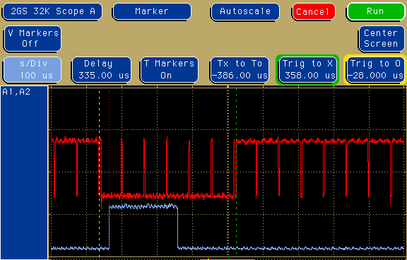
The resulting waveforms look like this. At the top, the composite video waveform from the Super Breakout PCB. In the centre,  the sync pulse at pin 1 of the LM1881 chip. At the bottom, the digital video ready to feed to the CPLD.

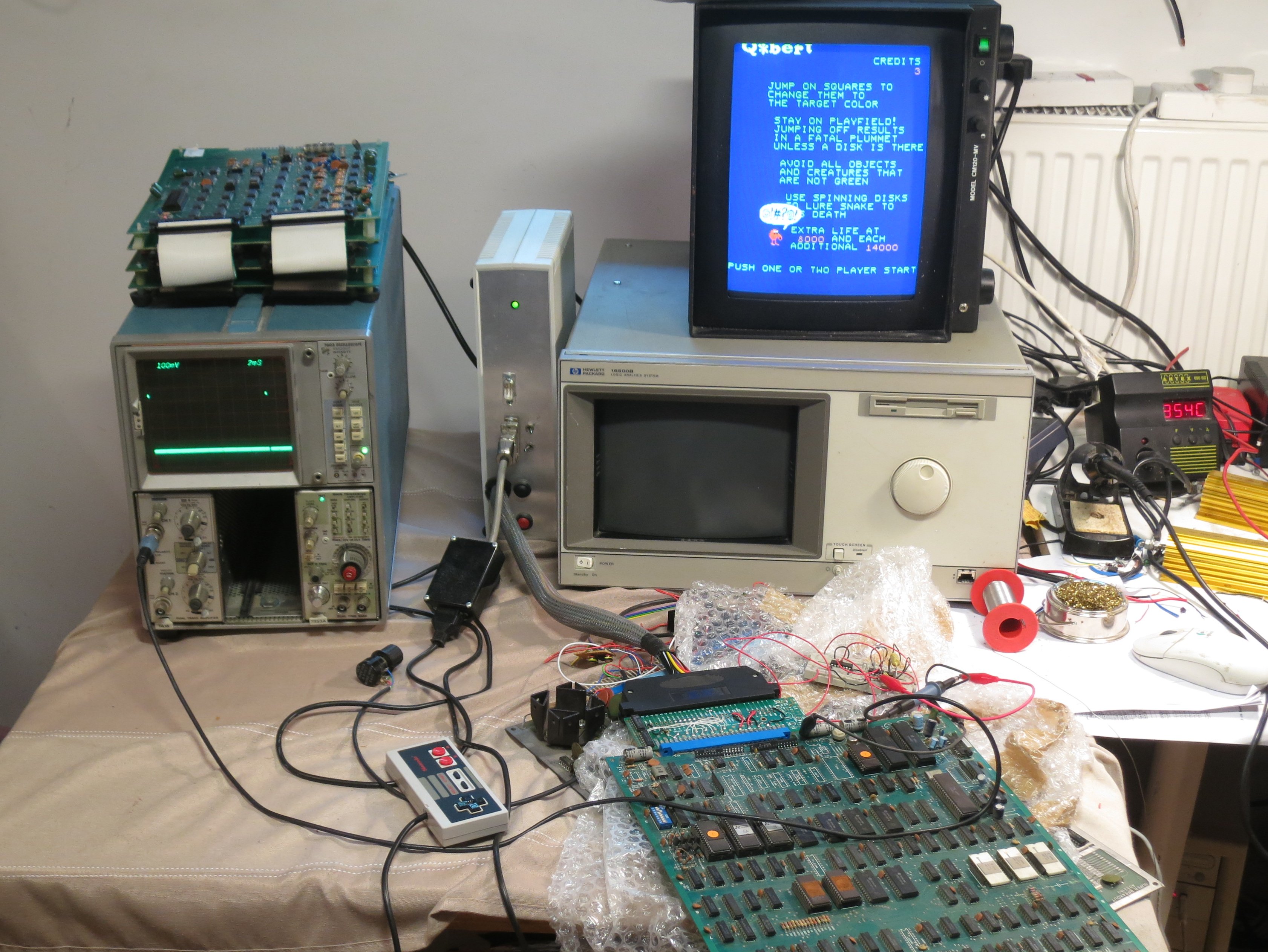
Here’s the circuit built on matrix board, next to the Lattice development board. There’s some more electronics at the bottom left, but more about that in another post.

img_20170215_215403

Generating the colour signal was relatively simple: a counter, clocked at about 6MHz, reset by the horizontal sync signal, indicates the position along each line of video. Some comparisons of that counter with fixed values decide what colour the output should be. A simple AND function of the colour with the video input and – lo and behold – a coloured screen! And no plastic film in sight.

img_20170215_215256


That syncing feeling: classic arcade games that won’t stay still

I’ve got a collection of classic arcade games from the ‘golden era’ of the early 1980s. They’re not the whole wooden cabinets with flickering lights and cigarette burns, but just the circuit boards from inside. They are easy to store and easy to plug in to a joystick and monitor to play.

However, some of them have always been a bit tricky to see. The monitor I use, a spiffy Microvitec bought surplus from Display Electronics in 1990, has fantastic picture quality but is a bit fussy about its input signal. Specifically, it seems to expect that the sync pulses – the bits of the signal which indicate where lines and pictures start – must conform more-or-less closely to broadcast standards. Unfortunately, the people who designed the old video games weren’t too worried about complying with standards. The result is that, on my monitor, some games tend to flicker and roll, or require very finnicky adjustment of the controls.

There’s loads of information about what video sync pulses are supposed to look like on the web.  This link has plenty of detail. However, the important things here turned out to be that the horizontal sync pulses should be fairly close to 4.7 microseconds long, and the vertical sync pulses should be pretty much three lines, or 192 microseconds, long.

I compared the outputs of various games – one which had never given problems (Mr Do’s Castle) with three which were troublesome (Phoenix, Pleiads and Q*Bert). The results were interesting. Here’s the vertical sync period from Mr Do’s Castle:

mrdocslv

In all the scope pictures, the red trace is the sync output from the game, and the blue line is the vertical sync from my electronics which I’m just using to trigger the scope at the right time.

In this case, the narrow red pulses are the horizontal sync pulses, and the broad area between the dotted lines is the vertical sync pulse. It’s six lines, or about 386 microseconds, wide, which seems to be good enough to keep the monitor happy.

Examining Pleiads and Phoenix, which have the same video electronics, here’s the horizontal sync pulse:

pleiadsh

Oh dear, It’s only 3 microseconds wide when it ought to be 4.7. And the vertical sync pulse?

pleiadsv

It’s a full eight lines wide, or more than 500 microseconds. Those numbers are way off what the monitor is expecting. The result is that the monitor refuses to give a stable picture, which makes playing the game very tricky:

Img_7793

Looking at Q*Bert, its horizontal sync pulses are nearly three times as wide as they should be, at 12.6 microseconds:

qberth

and Q*Bert’s vertical sync pulse looks like this:

qbertf

It lasts more than a millisecond! That’s miles off. The effect on the picture looks like this:

Img_7782

That’s as stable as I could get it. Notice how the left hand side (which is actually the top – the monitor is rotated 90 degrees)  is curved and wobbly. It was fairly hard to adjust the monitor to get the picture stable enough to take a photo.

There are solutions to these problems which involve modifying the game boards themselves, but I didn’t want to do that. I think they’re interesting historical artefacts (even the bootleg ones) and I try to keep them as original as possible. I wanted to fix the sync problems outside the board.

After a bit of experimenting, I came up with a little circuit which regenerates the sync pulses to be a bit more standard.

Img_7778

Untangling the rat’s-nest of wires, the schematic diagram looks like this:

syncfix-schematic

The circuit is simple and cheap, using two standard TTL logic ICs. It ought to work with 74HC series chips as well, but some of the resistor values might need changing. The diode is any common-or-garden signal diode: a 1N4148 or 1N914 is fine. It works like this.

  • IC1B is a monostable which triggers on every sync pulse, generating a pulse 4.7 microseconds long. These become the new horizontal sync pulses.
  • IC2B combined with D1, R3 and C3 form a sync separator which triggers the monostable in IC1C only on sync pulses which are longer than about 40 microseconds.
  • IC1C is a monostable which generates vertical sync pulses about 200 microseconds long.
  • IC2E combines the new horizontal and vertical sync pulses into a new sync signal.

The output isn’t what you might call broadcast standard, but it’s close enough to make the monitor happy. I’ve tried it on a few games and it works even on games which the monitor was happy with before. Here’s the results from Pleiads:

pleiadsc

Nice horizontal sync pulses, with a vertical pulse 193 microseconds long. There are a few extra pulses around but the monitor doesn’t seem to mind.

Img_7783

The results from Q*Bert are also good, though the vertical sync looks even more odd:

qbertc

The vertical sync pulse is a sensible length, but there’s a long pause after it before the horizontal pulses start again. That doesn’t bother the monitor, though, and all the wobbles have gone away. Here’s the test setup in use.

Img_7777Sorry about the mess, but at least the display on the monitor is tidy. Mission accomplished.

Motorboating in Space

zaxxon3

Or, how to stop Zaxxon going thump-thump-thump.

‘Motorboating’ has been a problem in electronics almost as long as electronics has existed. It gets its name from a characteristic thumping or buzzing noise, reminiscent of a motor boat’s engine. It’s a problem which usually occurs in audio amplifiers, and it happens either because of a design error or faulty components. Sometimes a change in an amplifier’s operating environment, such as a radio battery running down, can cause it. It’s loud, annoying, and can even damage speakers,

The reason for the noise is feedback. If an amplifier drives a signal into a loudspeaker, the power for that signal has to come from its power supply. Its power supply, especially if it’s a run-down radio battery, isn’t perfect. Drawing power from it makes its output drop in voltage for a moment. Unfortunately, electronic circuits aren’t perfect either. Their behaviour is strongly affected by their power supply. Connect such a circuit to such a power supply and amplifier, and you have a vicious circle: circuit sends a signal to amplifier, amplifier sends it to speaker and draws more power, power supply affects circuit, which makes another signal which gets sent to amplifier, and so on. It’s called feedback because the output signal feeds back into the input, via an unorthodox route. The circle of feedback can lead to the regular buzzing noise – the motorboating.

Recently I have restored a Zaxxon arcade game circuit board, which dates from 1982 (actually, it’s a bootleg, but the circuit is largely the same). I got it working well, but with one big problem: the sound was accompanied by a constant thumping noise which wasn’t supposed to be there. Here’s a short movie of how it sounded. It’s especially noticeable at the start and end of the clip.

Fans of the game will know that Zaxxon has very distinctive sound. Many video games at the time used digital techniques, often using standard chips, to generate their sound, which gives them a characteristic bleepy quality. Zaxxon is different. It uses what amounts to an analogue synthesizer: a magnificent assembly of timers, oscillators, amplifiers and filters. It has a lot in common with the kind of instruments used in pop music at the time. It makes a glorious, raucous noise.

IMG_3560

But this kind of analogue circuitry has a problem, especially when it’s cheaply built using early 1980s technology: it’s very sensitive to its power supply. Any variation in the power supply basically gets straight to the synthesizer’s output. What’s more, Zaxxon’s loudspeaker amplifier runs from the same power supply as the synthesizer. This lot is a recipe for motorboating, and that’s exactly what happened to my game.

zaxxon-power-1

Of course, we have to assume that it all worked properly when it came out of the factory, but then it would have been running from an official Zaxxon power supply. The one I use in my arcade game test rig may not be as good as the original one, but it’s good enough for most things, and I wasn’t going to change it just to fix this problem. So I had to come up with a modification to keep apart the amplifier power and the synthesizer power.

The traditional cheap and cheerful way of keeping power supplies apart, known as decoupling them, is simply to put a resistor and capacitor between them, like this:

DSC_0335

This decoupling means that variations in one power supply have a smaller effect on the other. It works well, and has been used in millions of electronic devices from the earliest days of radio. However, a certain amount of power is always lost in the resistor. Many circuits don’t mind this, or can be designed to handle it. I tried this approach with Zaxxon,and it turned out that the sound synthesizer doesn’t cope well with a reduced supply voltage. Many of the effects, especially explosions, became disappointingly quiet. I had to find another way.

Arcade games typically use two power supplies: 5 volts for their digital circuits, and 12 volts for the sound amplifier. This gave me an idea: how about using the 5 volt supply to run the audio synthesizer, keeping it neatly separate from the amplifier? Clearly the synthesizer wouldn’t just work from 5 volts: I’d already had trouble with it running from about 10 volts in the decoupling experiment. However, there was a solution. It would be possible to boost the 5 volt power supply up to 12 volts using, aptly, a boost converter. Boost converter modules are cheap and readily available thanks to low-cost far eastern manufacturing. The one I chose had a conveniently adjustable output voltage. It didn’t take long to wire it up. I’d already separated the amplifier supply from the synthesizer, and so I just had to take a wire from the existing 5 volt supply to the sound board, check my work and switch on.

zaxxon-power-2

It worked! The sound was now perfect, with no strange thumping effects, and everything seemed to be at the right volume. It remained only to make the modification more solid, and there was even a handy spare hole  to mount the boost converter in. Job done!

wpid-DSC_0326.jpg

Espial Arcade Game Pinout

espial

Getting through my collection of not-quite-working arcade PCBs, I’ve just sorted out ‘Espial‘ and made a JAMMA adapter for it. In the process, I discovered something missing from the available pinouts of this game online. In the game you have two weapons: you can drop bombs on ground targets, and fire lasers at flying targets. In MAME, the game uses two separate fire buttons, one for each weapon. However, the published PCB pinouts only show one fire button connection for each player. There’s a DIP switch setting which combines both bombs and lasers on to one fire button, which worked for me, but that’s not the same as having separate control of the weapons.

IMG_3734

I set about looking for the second fire button connections. The MAME source code shows that the second fire button for player 1 is in bit 6 of the port at 0x6081, the same port as some of the DIP switches. The inputs all seem to be handled by 74LS368 buffers. Prodding their inputs with a grounded bit of wire during a game revealed that the second fire button for player 1 was on pin 14 of IC2F. Aha! It does exist. Tracing the PCB tracks led me to pin E on the underside of the edge connector via R17. A similar process led me to pin G for the second fire button for player 2.

Here’s my updated version of the pinout diagram:

              COMPONENT  |  SOLDER
    ---------------------+----------------------
               GND   | 1 | A |   GND 
               GND   | 2 | B |   GND
                     | 3 | C |   
               +5V   | 4 | D |   +5V
                     | 5 | E |   1P.Laser
      Coin Counter   | 6 | F |   
           2P.Down   | 7 | G |   2P.Laser
              Coin   | 8 | H |   
           1P.Bomb   | 9 | I |   Service
          1P.Start   |10 | J |   2P.Start
           1P.Left   |11 | K |   1P.Right
             1P.Up   |12 | L |   2P.Up
           2P.Left   |13 | M |   2P.Right
           2P.Bomb   |14 | N |   1P.Down
               GND   |15 | O |   GND
               Red   |16 | P |   Green
              Blue   |17 | Q |   Sync
                     |18 | R |   Speaker
                     |19 | S |   
              +12V   |20 | T |   +12V
               GND   |21 | U |   GND
               GND   |22 | V |   GND

I also found that it was important to connect up all the power and ground connections, even the seemingly duplicated ones, before the game would start up correctly. But start up it does, and it’s fun. I hope this information is useful to someone.

Img_3737

Super Pacman repair log

I’ve just got an old Super Pacman arcade game running. Not the whole cabinet, you understand, which would be inconveniently large, but the circuit board from inside one, connected up to a monitor and joystick.It’s the lesser-known 1982 sequel to Pacman and Ms Pacman. It’s a fun game, with more complicated gameplay than the original: gates, keys, a speed-up button and a special powerup which makes you really big and able to go charging through everything. I could find hardly any repair information about Super Pacman on the internet, so I thought I’d paste my repair log here so people can see it.

Firstly, as part of the process, I pasted together large high-resolution circuit diagrams by cutting and pasting from the available PDFs of the manual in which they’re sliced up into pages. The ones I’ve stuck together are more convenient to use when printed out on large sheets of paper or viewed on a big screen. I hope they’re useful.

super-pacman-cpu-hires

super-pacman-graphics-hires

Super Pacman repair log

1/1/2013

Connect up power and video. Occasional flashes of something on the screen but no sync. Main clock oscillator is running.

Lack of sync output seems to be due to unenthusiastic 74LS10 at 3A. Output at pin 12 is weak. Vertical sync input at pin 13 is OK but H sync input at pins 1 and 2 is very poor – barely leaving +5V but pulses are visible. Comes from a custom chip 2C. Hope it’s not knackered. Cut pins of LS10.
Output of custom recovers.

Replace 3A. Now we have a picture of random junk in blue and green which wriggles a bit when reset button is pressed.

Why does there appear to be no red in the picture? There’s activity on R video pin even though pin 1 of colour PROM 4C has snapped off. Maybe a blanking problem.

2/1/2013
RGB outputs are high during what should be blanking interval. Investigate inputs to PAL 4D. 6/7/8/9 are all stuck high. They come from 74LS298 4L, whose inputs looks pretty sensible but outputs are all stuck high. Remove it ready for replacement.

Blanking signal from 3A pin 6 ends up at PAL 4D pin 19 and seems to force its outputs to 01111. In this state, output of colour PROM 4C is 10101111. That’s definitely wrong according to the MAME ROM image. Should be 00000000.

Can’t buy or program PROMs easily so try substituting with a high-speed OTP PROM: Atmel 27C512. Physically large but cheap and easy to program, 45ns access time is OK. Wiring:

82S123 27C512
O1   1  O0  11
O2   2  O1  12
O3   3  O2  13
O4   4  O3  15
O5   5  O4  16
O6   6  O5  17
O7   7  O6  18
GND  8  GND 14, 1,2,3,4,5,21,22,23,24,25,26,27
O8   9  O7  19
A0  10  A0  10
A1  11  A1   9
A2  12  A2   8
A3  13  A3   7
A4  14  A4   6
nCE 15  nCE 20
VCC 16  VCC 28

Now colours are sensible. Maybe 4L (74LS298) isn’t faulty after all – It might just be that no sprites are displayed so there’s no activity.

IMG_3556

PROM at 4E is losing pin 1. Need to sort it out.

10/1/2013
Try and work out why game doesn’t run. Activity on data and address buses. EPROMs 1 and 2 (1B and 1C on CPU board) verify OK. When it stops, it’s resetting the watchdog continuously!

Sound CPU isn’t running cos its reset input (37) is low. Comes from latch 2M (74SL259). Pulling it high for a moment makes it stay high, oddly.

15/1/2013
Repair pin 1 of PROM 4E with Dremel and bit of wire. Screen of random characters looks more and more sensible: the word ‘CREDIT’, or bits of it, seem to be appearing in places.

Replace suspect 74LS298 at 4L now replacements have arrived. Makes no difference at all.

18/1/2013
Start examining buses and their buffers. Buffered address bus (from CPU board 2H, 1H, 1E) looks OK but buffered data bus has some bits hanging around near 0 where they should be pulled high. Disconnect the two boards and the fault is definitely on the video board. Could be any of 74LS245 1E, 1K, 1J, 1H. Remove them all. Replace them with secondhand chips. Board still doesn’t run but pattern on screen is somehow a bit different. RAM fault? Piggybacking RAMs doesn’t have any
effect.

19/1/2013
Chip at 2E (Namco 04xx) seems to be associated with addressing the RAMs. We have replacements on some Pole Position boards. Try swapping it and results are definitely different: instead of just random characters, there are now random sprites as well. Try two different 04xxs (0429 and 0436) from Pole Position and they both behave the same. Assume they’re OK then
and the original is faulty. Game still doesn’t run. Can’t see any dodgy logic levels on video board and piggybacking RAMs doesn’t help.

Still no interrupts happening. 74LS259 at 2M on CPU board is behaving oddly. It is being addressed but none of its outputs are changing, but if I pull any of them high for a moment they stay high.

When CPU crashes, it sits in an 8-cycle loop. Record what’s going on.

A EEEEEEE8
  11F111F0
  77F777F0
  BCF89AF0
D 2F0B8003
  0B070001

A15 11111111
A14 11111110
A13 11111110
A12 00100010
A11 00100010
A10 00100010
A9 00100010
A8 11111110
A7 00100010
A6 11111110
A5 11111110
A4 11111110
A3 11111110
A2 01100010
A1 10100110
A0 10101010
D7 01011000
D6 01000000
D5 11010001
D4 01010001
D3 01000000
D2 00010000
D1 01010000
D0 01010001
RnW 11111110

It’s in a tight loop at E178-E17F, which finishes by writing the value 0x31 to 0x8000. That’s the address which resets the watchdog.

Analysing the code in MAME, it seems that the first part is a RAM test which copies the ROM (from E000 onwards) into the RAM and reads it back, comparing it with the ROM. If it fails, it will try to put up the self-test screen indicating which RAM has failed, then go into the loop at E178. A value of 0x31 in A I think indicates that the tilemap RAM has failed, at 2E on the video board. So it seems that the first RAM test is failing and it’s trying to tell us about it, but access to the video RAM is so broken that we can’t see it. The CPU is actually running correctly.

Replace RAM 2E. Doesn’t make any difference, but if I remove buffer 1E the screen should clear with after the RAM test. It doesn’t, and behaves a bit randomly. Remove custom 00xx at 2D, which is the video address generator and thus has the ability to mess up video RAM addressing, and game appears to run! But tilemap is all the same character, not surprisingly because nothing’s generating video addresses. Pin 1 has dropped off 00xx. Temporarily connect it with scalpel and we have action. Repair pin 1 properly and game runs.

Try inserting coins by tickling edge connector with grounded wire. We can start a game and control Pacman. Pinout seems to be the same as Grobda but with player 1 and player 2 swapped over.

Wire up single player JAMMA adapter. Sound works! Pleasant surprise. Some sprites sometimes become white squares, but reseating customs on video board solves the problem.

Game fixed.

Img_3558

Replacing Bipolar PROMs

Back in the 1970s and 1980s, digital electronics made quite a lot of use of Bipolar PROM chips. They are a memory device, which can be programmed just once, holding only a few hundred or a few thousand bits of information. They were used for various tasks: address decoding, state machines, and video colour palettes, for example. They are very commonly seen in vintage arcade games and in other electronic devices too. Like any electronic component, they sometimes fail. They can be hard to replace, because they are no longer manufactured, and they are not supported by many low-cost device programmers. In addition, the legs seem to fall off them. Here’s a dud one which came from a Super Pacman PCB:

IMG_3552


These things carry part numbers like MB7051, 74S288, AM27LS09, HM7603, 82S123 and 82S129. Some are available secondhand but they’re expensive, and programming them is a pain. My EPROM programmer (A cheap USB GQ-4X) doesn’t support them. This one needed replacing. What to do?

Apart from coming in small packages, these things have another attribute: speed. They typically respond in around 40-50ns or less, which is much faster than most EPROMs or Flash memory chips. However, whilst investigating alternatives, I found that fast PROMs still exist, just about, in the form of one-time programmable ROMs. I chose an Atmel 27C512 because it’s compatible with my programmer, readily available (thousands were in stock at the distributor I use) and very cheap – less than £2. It also has a 45ns access time, making it a worthy substitute for the dead MB7051 in the picture. It’s a bit big, coming in a 28-pin DIL package, but it has more than enough memory space: 512kbit. That’s 2000 times bigger than the original chip!

To adapt it to the Super Pacman PCB, I first programmed it (or the first few bytes of it, anyway) with the correct data, obtained from a MAME ROM dump of Super Pacman. Then I made a little carrier board out of some stripboard and PCB pin strips (Harwin pins, Farnell part number 1022218, are thin enough to go into chip sockets without damaging them) and wired the whole lot up with fine polyurethane-insulated wire. The wiring went like this, noting that many of the address pins are unused and therefore grounded:

82S123 27C512
O1 1 O0 11
O2 2 O1 12
O3 3 O2 13
O4 4 O3 15
O5 5 O4 16
O6 6 O5 17
O7 7 O6 18
GND 8 GND 14, 1,2,3,4,5,21,22,23,24,25,26,27
O8 9 O7 19
A0 10 A0 10
A1 11 A1 9
A2 12 A2 8
A3 13 A3 7
A4 14 A4 6
nCE 15 nCE 20
VCC 16 VCC 28

and the result looked like this:

IMG_3554 IMG_3553

Switching the game on, I was greeted with a display with the correct colours and plausible-looking characters!

IMG_3556


Shame it doesn’t actually run yet, but it’s much better than the green and blue splodges it used to produce. Onwards and upwards.