Monthly Archives: April 2013

Dangerous Counterfeit Mains Cable

The other morning I went to plug in a piece of equipment on my work bench. It needed a standard IEC-type power cable. My workshop, like many others, has a box in the corner containing an assortment of such power cables. I can’t remember where most of them came from, and I just grabbed the first one.

It seemed rather short, only about one metre long. That didn’t matter for this job. But I noticed that the insulation was damaged near the IEC connector. Oh dear. That makes the cable unsafe to use, so I set about destroying it before throwing the parts away. My usual technique for that is to put one foot on the plug and pull hard, tearing the cable out and rendering the whole thing unusable scrap. But I got a surprise: the cable more or less came apart in my hands!

I examined it more closely and found the oddest colour code I’ve ever seen:

DSC_0466

Where on earth is the mains wiring colour code blue, black and black with a turquoise stripe? Not anywhere in Europe, that’s for sure. I looked further, taking the fuse out of the plug. Sharp-eyed readers will already have noted that the fuse is rated at 3A but coloured brown. That’s an oxymoron: under the British Standard BS1362, 3A fuses are red and 13A fuses are brown. So which was this one? It certainly doesn’t comply with the standard in spite of the ‘BS1362’ written on it.

Time to test the fuse. I hooked it up to my big power supply, and cranked up the current.

DSC_0471

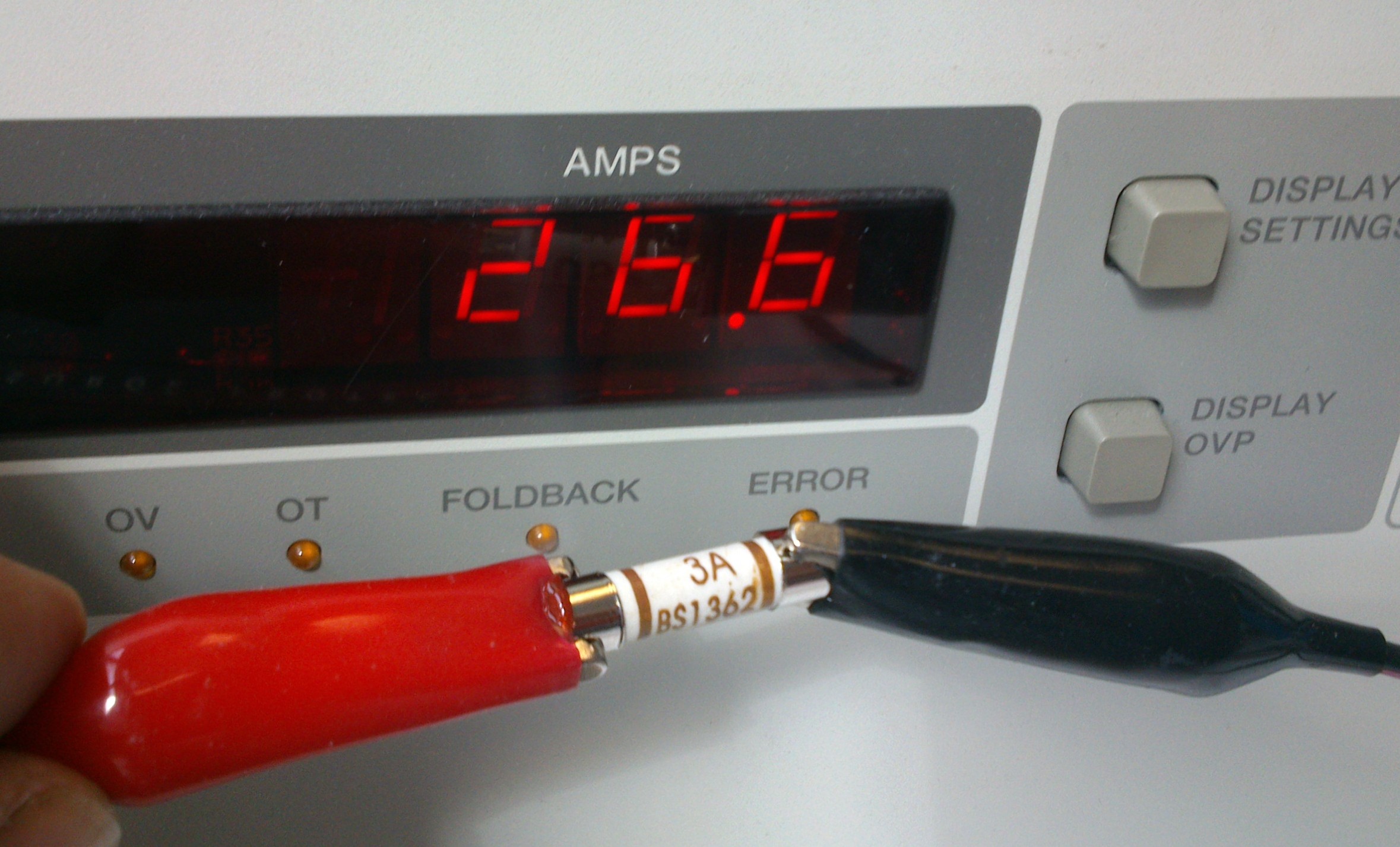
Yes, you read it right. This fuse labelled ‘3A’ carried 26.6A for long enough for me to pose it for a photo, pick up the camera and press the button. It blew a few seconds later. That’s the sort of behaviour I’d expect from a 13A fuse, not a 3A one. Oh dear.

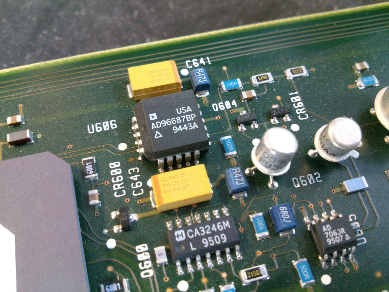
I went back to the cable, and noticed that I could easily pull apart the insulation – both the thick outer and the inner cores – with my bare hands. No tools required, not even fingernails.  That’s unbelievably dangerous. Once I’d peeled some insulation off, there was hardly any copper inside the wires:

DSC_0472

My finger-in-the-air estimate of the safe current carrying capacity of this wire would be less than 1A.

What a cable. The connectors on both ends (which I forgot to take a photo of) were covered with various approval logos. I can’t believe this thing met any safety standards. The wire itself was so weak that it could be peeled back to bare copper with just my fingers. The plug fuse was mislabelled and far too large for the rating of the cable. The cable was so thin it wouldn’t handle the load that an IEC connector is designed for without dangerously overheating. If a fault had developed in the appliance plugged in with this cable, it’s likely that the cable would simply have caught fire before the fuse blew.

I believe that this cable was supplied with a Chinese USB hard drive enclosure I bought a few weeks ago, but I can’t prove it. If you buy cheap electrical goods, check the mains cable carefully. I don’t know whether to call this one fake, counterfeit or just bad, but it was certainly a death trap.

Bubble Development Board Ethernet and SD working

I’ve got a couple more features of the Bubble development board working. The Micro SD card needed pullup resistors from its data and command/data lines, then it Just Worked though the card detect function doesn’t do anything yet. While modifying the VHDL to get Ethernet working (see below) I noticed a message that sd_card_detect has been optimised out of the design because it’s not connected to anything. That would explain it. I’ll look at it in a while. I’m not even sure whether the kernel driver supports a card detect line.

Most excitingly, Ethernet works now. I’ve connected its interrupt output to a register in the CPLD and modified the platform code in the kernel to point it at the relevant interrupt, and it works! It gets an address by DHCP and I’ve successfully copied files to and from it by scp. It seems a bit slow, topping out at about 3.5Mbit/s, but the Samosa bus timing is pretty relaxed and could probably be speeded up significantly. I saw one transmit timeout message, too, so maybe something isn’t quite right yet. Oh, and the MDI/MDI-X negotiation still seems a bit unhappy so the link doesn’t come up every time.

I’d also like to wire the ‘link’ output of the W5100 to a GPIO so that the driver can see it and do sensible things when the cable gets plugged in and unplugged.

Raspberry Pi Power Architecture

Embarking on some work with the Raspberry Pi recently, I wanted to know what its power architecture looked like. The schematic diagrams are freely available but a quick web search didn’t reveal any higher-level design documents like this, so I drew my own and here it is.

I offer no guarantees of accuracy. Don’t blame me if you use this documentation and destroy your Raspberry Pi or anything else. This is not an official document. I hope it’s useful to someone.

The original version of this that I posted in April 2013 had a mistake in it, which Kai kindly pointed out. The version below has been corrected.

Raspberry Pi Power Architecture2

There’s a nice shiny pdf of it here: Raspberry Pi Power Architecture

Bubble Development Board – progress

Having now had the Bubble Development Boards for a few days, I’ve tested a few more features.

Both JTAG sockets (Xilinx 14-pin and ARM 20-pin) work with their respective dongles.

The Ethernet adapter, a Wiznet W5100, is showing signs of life. If I plug an Ethernet cable into it, the ‘link’, ‘full duplex’ and speed indicator LEDs come on. Frequently the ‘link’ LED blinks continuously along with the Rx LED. I don’t know why, though searching on the web indicates that the W5100 can be fussy about the choice of transformer it’s used with, and sometimes about what kind of hub it’s plugged into – apparenly the automatic MDI/MDI-X negotiation can get confused. The tests were done with a TP-Link TL-SF1005D switch and I haven’t tried any other. Sometimes, though, the link will settle down to a steady state, then I see the Tx and Rx LEDs doing sensible things.

DSC_0453

The W5100 chip is wired to the Samosa bus with very simple address decoding so that it should appear every 4 bytes across the whole 256-byte Samosa address range. Manually poking and peeking its registers from the Bubble board’s boot loader gave sensible results, and I even managed to get it to try and send a packet, the Tx LED blinking reassuringly.

Recent Linux kernels have a driver for the W5100. I tried kernel version 3.7.1 which has already been patched for the Bubble board. The existing drivers expect the chip to be I/O or memory mapped, which is not the case on this board because it’s on the Samosa bus. The Samosa bus is accessed using its own function calls inside the kernel. I patched the driver, and had to undo one or two assumptions made in the code about memory access, and the results are promising: the chip is found correctly, interface eth0 appears, and it even sends packets from the DHCP client attempting to get itself an address. However, the first attempt to send a packet results in an error:

NETDEV WATCHDOG: eth0 (w5100): transmit queue 0 timed out

and a stack trace, though the kernel carries on running. It seems that the Ethernet chip’s interrupts are not making it into the kernel. This turns out to be due to the offending interrupt line not being connected to anything in the Bubble board’s CPLD, so I’ll have to fix that next. That needs the Xilinx programming dongle which I haven’t got with me at the moment.

Bubble Development Board – first prototypes received

A couple of days ago I received the first examples of the Bubble Development Board and started testing them.

DSC_0420

Much to my joy, the board fits neatly into a low-cost plastic case from Farnell, part number 1526699. With front and rear panels suitably cut out, it should be well protected and easy to connect things to.

DSC_0421

But does it work? Well, yes, largely. Here are the results so far.

  • Power: the LEDs (green for +5V input, orange for VDD_IO from the Bubble) come on and the Bubble board starts up reliably.
  • Reset button: does what it says on the tin.
  • Serial port: console works.
  • USB host: tested to work with a memory stick and a USB-to-Ethernet adapter.
  • USB slave: working. USB networking connection successfully established to a desktop PC as documented at http://www.balloonboard.org/balloonwiki/USBNetworking.
  • Audio: output works, straight into a pair of headphones, and quality seems good with no unpleasant background noises. Haven’t tried input yet.
  • HDMI: the Bubble board I was using was set up to drive an LCD panel, but by installing fbset and fiddling around with the settings (making them roughly 800×600, 60Hz) I managed to get a display on a monitor connected to the HDMI port. However, the image tends to disappear every few seconds and then come back again with some flickering, so something’s not quite right. I tried another monitor via an HDMI-DVI cable with the same result.
  • Micro SD socket: not working yet. The kernel reports an error during boot and /dev/mmc* devices don’t appear. I’ve noticed that other implementations of the SD card socket from Bubble have pullup resistors on all the data and clock lines which I neglected to put on this board. This might be an easy fix because the wiring looks right.
  • JTAG, Samosa, Raspberry Pi header, Ethernet: not tested yet.

Here’s another picture with the Bubble board turned over so you can see what’s on it.

DSC_0422

HP 16534A triggering problems

DSC_0404

One of my HP 16500B logic analysis systems has a 16534A digital oscilloscope module installed. The module has a great specification: two channels, 2Gsamples/sec, 500MHz analogue bandwidth, and 32k record length. I would find it a really useful debugging tool, if it worked properly. Sadly it doesn’t.

Though it displays a trace successfully, and the controls work, it won’t trigger. The only way I get a trace is by auto-trigger. In this case the trace isn’t synchronised, so it’s impossible to catch a particular event at a particular time. Here it is displaying a square wave (well, it’s nearly square – I hadn’t adjusted the probe compensation so it’s a bit curvy on the top and bottom). Adjusting the trigger level just doesn’t make any difference.

DSC_0409

The service manual for the 16534A isn’t very helpful. It describes roughly what the self-tests do, and how to run the self-calibration procedure, but has no detailed circuit information. The self-test reports a ‘D/A’ failure:

DSC_0405and the self-calibration procedure fails on the Trigger and Hysteresis sections:

DSC_0406

The service guide describes the D/A test like this:

Test DAC This test verifies the correct operation of the D/A convertor on the board.
Both the offset and trigger level D/A convertors for each channel are set to a reference
level and then changed. The logic trigger IC is programmed to detect the changes. The
detection of a correct trigger indicates that the D/A convertor is operating normally.

It seems clear that the offset D/A converter is working, since the offset control works and moves the trace up and down as it should. However, the trigger level control doesn’t seem to be doing what it should. I had a look at the board, looking for components likely to be the DAC or trigger IC. Unfortunately, the semiconductors on there seem to be mostly either standard ECL logic, trivial things like op-amps, or magic custom HP chips with dozens of pins. One exception was this:

DSC_0410

It’s an AD96687 from Analog Devices, which is a dual high-speed comparator with ECL outputs. If I was designing a high-speed trigger circuit using 1994-vintage components, I might use a device like this. I’ve had a look at all its pins with the power switched on and a signal applied and tests running, and none of them seem to change at all. One noninverting input is stuck at +5V, and the other inputs are near ground. One set of outputs isn’t even showing valid ECL logic levels, but it may be unused and thus have no load resistors on it.

Maybe it’s a red herring and nothing to do with the triggering at all, but I’m suspicious that I never see anything change. Without more circuit information, it’s hard to get much further, sadly.