Monthly Archives: June 2013

Tektronix 549 Storage Oscilloscope, part 6

In part 5 I repaired the damage I’d done to the ‘enhance’ feature. The ‘locate’ button was the next problem to solve. It was really sensitive and tended to get stuck in the pressed position.

IMG_5007

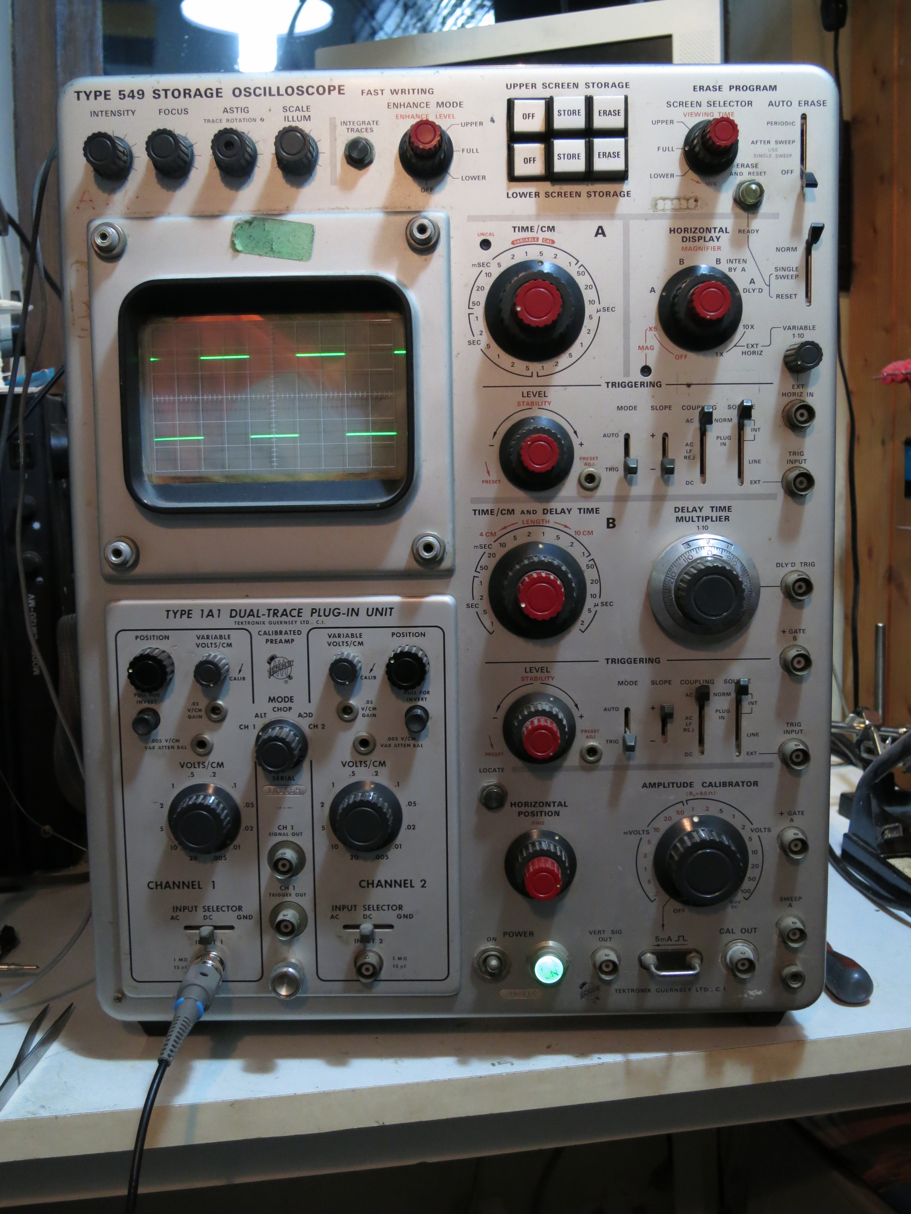
Its job is to let the user see where the trace has gone, or where it might appear. It’s necessary because the oscilloscope has dozens of controls – probably more than a hundred – and if any of them isn’t set right, the usual result is a blank screen. The locate button helps by squashing the trace in from all four sides and cranking the brightness up to maximum, so you can see whereabouts the beam is pointing. Here’s a picture of a normal trace (a video output from a BBC micro, as it happens) and what it looks like if I move its vertical position way up off the screen and press ‘locate’. You can see that a squashed version of the trace appears near the top of the screen, so I know I should move it down to see it properly.

IMG_4999 IMG_5001

The 549 has an extra feature, though. Because it’s a split-screen storage oscilloscope, it’s expected that it will often be used in single-sweep mode: waiting for a trigger signal, then recording a trace once, then stopping so you can see it. While it’s waiting for the trigger, there’s nothing to see on the screen. It would be helpful to have some idea where the trace will appear when the sweep starts, to make sure it will actually be captured.

Tektronix, typically, thought of this problem. The locate button behaves differently when either of the ‘store’ buttons is pressed. In this mode it simply moves the beam into a special non-storage area on the left of the screen and turns up the brightness but leaves its vertical position unchanged. In this way you can see where the trace will start when it triggers, but without trampling on the storage area. Neat. Here’s a picture of the same video waveform as above, correctly positioned but with the timebase in single-sweep mode, storage enabled, and ‘locate’ pressed. You can see the shape of the trace on the left, out of the storage area.

IMG_5004

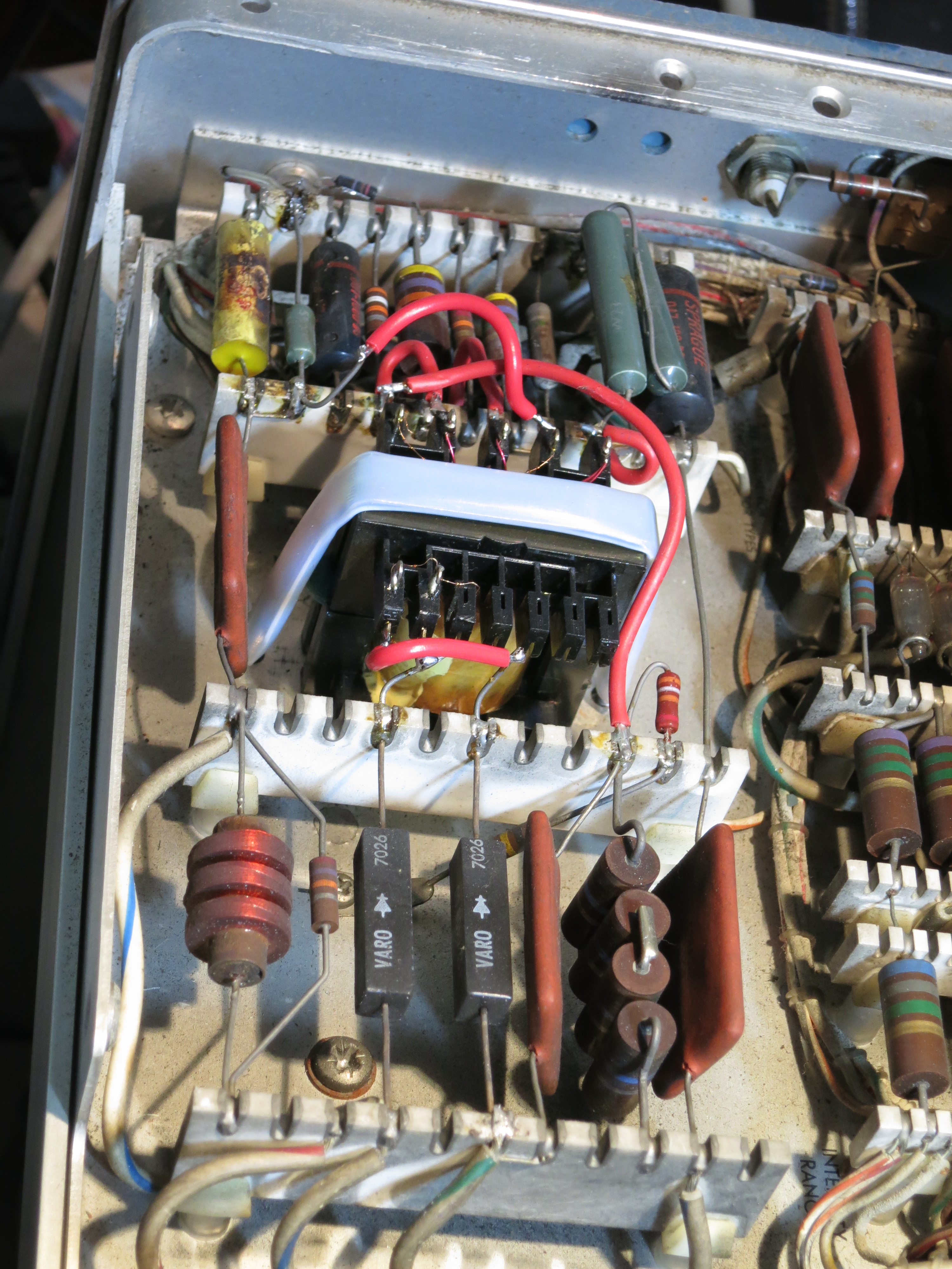
Of course, to achieve this, the locate button has several contacts affecting various parts of the circuit. It’s buried deep inside the scope behind the front panel, and is a pain to get at. I managed to remove it and found that one of the brass contacts which also provides the spring action had fractured and actually fell off when I touched it. That would explain why it was getting stuck.

Img_4684

I considered replacing the switch with something else, or a relay, but realised that by dismantling the existing switch (it was strung together like a kebab with two screws), rearranging the contacts a bit and soldering a couple of them together, I could repair it. It took a bit of experimenting with the paxolin spacers until the action was right and all the contacts did what they were supposed to, but it was a success. After reinstalling the switch, which involved some tricky soldering at close quarters, it all worked as it should.

Img_4687

Time for the finishing touches. I gave the case a good clean and got out the tinsnips to make a new cover for the EHT compartment because it was missing. I had to guess what it looked like from photos, but I added an insulating sheet of plastic on the inside to reduce the risk of a high-voltage flashover from the transformer pins or anywhere else.

DSC_0517

DSC_0519

With a quick clean of the case and knobs and a replacement mains lead (the old one was perished and cracked and wouldn’t pass a PAT test) this magnificent machine is ready for use once again.

Tektronix 549 Storage Oscilloscope, part 5

In part 4, we’d got the delayed timebase working thanks to swapping out a pair of 6AU6 valves. But there was still something not working, and it was all my fault. I’d killed the ‘enhance’ feature.

IMG_4690

The 549 is special because it’s capable of capturing an event which takes place in less than a microsecond, and storing it so a human viewer, or a film camera, has time to see it. There’s no digital memory or computer here: the storage is done in the cathode ray tube, directly on the screen. By an amazing feat of electrostatic trickery, it’s possible to put the screen into a mode in which electrons hitting the screen at a point will ‘bump’ the phosphor screen at that point into a different state, and it’ll stay like that – it’s a bistable phosphor. Then, by gently sprinkling electrons all over the phosphor from a flood electron gun, the bits which have changed state continue to glow. In this way, as the electron beam sweeps across the screen tracing out the waveform, it can leave behind a visible trail. It’s possible to erase the trail later by winding up the power of the flood gun for a moment, and bumping the phosphor back into its normal state.

This is some pretty advanced physics, and it’s very analogue: lots of bits of metal inside the tube at precisely-controlled voltages throwing electrons around in a high-speed game of ping-pong so they end up in the right places, with the right energy, at the right time. Tektronix, forever at the bleeding edge, wanted to extract the last possible bit of performance from this finely-tuned and expensive system. As the electrons hit the phosphor, it takes a certain number of them to get it to change state. If the beam is sweeping too quickly, there isn’t time for that to happen, and so the trace doesn’t get recorded. However, it turns out that if the whole screen gets a bit of a ‘kick’ from the flood gun before recording starts, it gets more sensitive for a moment, so it can record faster traces. The specifications quote a writing speed of 5cm per microsecond, which is pretty swift. I reckon it’s roughly equivalent to 100 megasamples per second in a digital oscilloscope. Digital scopes took another 20 years to get that good. The 549 was released before Sgt Pepper’s Lonely Hearts Club Band.

This ‘kick’ to wake the screen up is provided by the enhance feature. A couple of transistors generate a precisely-timed pulse just before the sweep to get the screen ready and poised to catch the electrons. Or, at least, that’s what should happen. It turns out that if a clumsy repairer accidentally short-circuits the 500 volt power supply to the input of the enhance circuit, it dies.

IMG_4660

I killed D1134, Q1135, Q1145 and D1146 in one swift move. The damage stopped there because the next component in line is a valve, which shrugged off such a minor trifle as an accidental half a kilovolt.

The diodes were simple to replace. I used 1N4148s. The transistors looked uncritical enough, and I put a couple of 2N3704s in. But the circuit didn’t work. No pulse came out, and no enhancement happened. I looked again at the design, and it seems that the gain hFE of the transistors, especially Q1135, is critical.

The transistor Q1135 is biased by R1133 and the ‘enhance width’ control R1132. Normally, it should be switched on, and when a negative-going pulse from the trace flyback blanking arrives via C1131 on the left, it should switch off for a moment and generate a pulse. However, the gain of my replacement 2N3904 was too high. The current glowing through R1132 and R1133 was enough to keep it switched on all the time, even when the blanking pulse arrived. Result: no ‘enhance’ pulse output.

The manual says that the original transistor is equivalent to a 2N918, which has a gain of about 50. I didn’t have any of those, and they’re long obsolete. But there’s another half a dozen of them on this board doing other jobs, so maybe I could swap some from there and use my newer transistors for another job. A quick look at the circuit revealed this:

Img_4661

Here are two transistors, Q1033 and Q1043, just being emitter followers from the erase controls. It really wouldn’t matter what their gain was, as long as it was enough. A quick swap and…success! Both erase and enhance worked as intended.

It’s very handy that the transistors in this machine are all in sockets. Interestingly, the old ones look like they’re in TO92 packages:

Img_4663

But their pinout is the opposite way round to modern transistors, which have to sit facing the wrong way in the socket with their legs bent.

Img_4662


So far so good. There are still a few problems to sort out, though. The ‘trace locate’ button is ridiculously sensitive, so you barely have to breathe near the scope and the trace shrinks into a little rectangle in the middle of the screen, which is annoying, and the whole thing is filthy dirty. Timebase A’s triggering seems a bit jittery at high speeds, too.


Tektronix 549 Storage Oscilloscope, part 4

In part 3, the scope was working, with a trace that seemed to do the right things. But the delayed timebase was dead. It’s a handy feature that effectively lets you select a part of the waveform on the screen and zoom in to magnify it, and in today’s digital world it seems almost inconceivable that it was possible to do such things with analogue electronics.  Mind you, it takes quite a lot of analogue electronics to achieve it, especially with valves. The 549 contained an outrageous 53 valves when I counted them. In the photo below, the swung-out panel on the right is basically devoted to the delayed timebase.

IMG_4654

There’s a part of the circuit called the ‘delay pickoff’ which is responsible for selecting which part of timebase B’s sweep to magnify or, more accurately, when to trigger timebase A. It contains a comparator, which compares the sweep voltage as the beam scans across the screen with another voltage, which you set by turning the ‘delay multiplier’ knob on the front panel. When the two match, it sets a flip-flop, which triggers timebase A. In this way, you can choose where on the screen to start the timebase by turning the knob. Handy.

I started probing around with another oscilloscope to see what was going on, or not going on. The circuit diagram in the manual is full of helpful voltage readings and waveforms so you can see what should be there at various points.

IMG_4656In this case, I found that there was a nice sweep sawtooth on the grid of V414 at the left hand side of the diagram, but instead of a sweep on pin 1 of V428A (the blue waveform), I just had about -120V. The grid of V428A was also at about -125V, when it should be held at -100V by R425 and R426. Aha, I thought, R425 has gone high in value! These old carbon resistors do that. So I checked it – no, it’s fine. Then it must be V428A that’s faulty! I even proved it by removing it from its socket, and the voltage at pin 2 returned to -100V. I borrowed a known good 6DJ8 from elsewhere and triumphantly fitted it. Switch on and…no change. Hmm.

If V414 and V424 both have 225V on their anodes and -120V on their cathodes, they’re clearly not conducting much, or they’d probably have melted. I swung open the panel that they’re mounted on and had a look at them. V424 wasn’t glowing, and felt cold! I gave it a wiggle in its socket and it started to glow, and immediately the voltage at its cathode went up to about +30V. Found the problem! But still there was no sawtooth waveform there, just a voltage which varied as I turned the delay multiplier control.

I carefully cleaned the pins and sockets of V414 and V424 but it didn’t help. I thought I’d try swapping them over, to see if anything changed. For no particularly sensible reason, I did it with the power switched on, and I’m glad I did: as I put the second one back into its socket, I noticed purple flashes from inside it! That’s not supposed to happen. One of the 6AU6s is very sick. Here’s the guilty party.

IMG_4657

I borrowed a 6AU6 from another scope, and there was an improvement: the delayed timebase started to work, but the range was all wrong. It would start the delay half way across the screen, and it was impossible to adjust it properly. I replaced the other 6AU6 as well and it worked much better. I was able to adjust the delay start and stop controls so each notch on the delay multiplier knob corresponded to one division on the screen, just as they are supposed to. Here’s a picture of the delayed timebase working. It’s in ‘B intensified by A’ mode, and you can see the brighter section of trace.

IMG_4658

Time to go shopping for a pair of 6AU6s.

Tektronix 549 Storage Oscilloscope, part 3

In part 2 I established that there was something wrong with one of the windings on the replacement EHT transformer, so the grid voltage was either too low, leading to a very dim trace, or too high, leading to a trace which was too bright. The only way to fix this problem was to modify the transformer. Knowing that it’s a tricky device which has to handle high voltages, it was with some trepidation that I took it out of the scope and dismantled it.

IMG_4633

Whoever made the transformer knew what they were doing. They’ve taken care to put a gap in the core to prevent it saturating – notice the plastic washers used as shims between the two core halves. Looking at the circuit design, I believe that this power supply is running as a flyback converter, so a gap in the core is required. Everything is nicely taped up and varnished, and there is paper tape in between the layers of the windings, too, for good high voltage insulation. I was relieved to see all this: it makes me feel confident that a repair is worth doing.

It seemed clear that one winding, the one generating too large a voltage on the grid, had too many turns on it. I had to work out how many turns to remove. I’ve been designing some flyback converters for another project recently, so I could make an educated guess. I’d expect a transformer like this one to run at somewhere around 1 turn per volt, maybe more, maybe less. I want to reduce the grid winding’s output by about 50 volts, so I thought I’d start by removing 20 turns from it.

I put the transformer in the oven to soften the varnish so I could dismantle it (150 degrees C for about 15 minutes). Unwrapping the winding, removing 20 turns was easy – they were all on the first layer, so I only had to unpeel one layer of tape. I temporarily put the transformer back in the scope and tried it. Success! I could follow the instructions for setting the intensity in the manual: set to single sweep, so the trace should be blanked, turn the front panel intensity control to maximum and adjust the internal intensity range control so the spot is just visible. It was well within the range of adjustment of the control.

With the EHT working properly, I checked the voltages: the cathode is fixed at -3700V. For normal trace brightness the grid is at about -3750V, and about -3800V hides the trace entirely.

Incidentally, I was mistaken about how the intensity control works in my comments in part 2. Having studied it more carefully, the EHT supply regulates the cathode voltage to be -3700V. The intensity control varies the voltage on the ‘top end’ of the cathode winding between about +10 and +100V so the power supply has to work more or less hard to maintain -3700V at the cathode. That results in the voltage on the grid winding varying by about the same amount, so the intensity varies.

I also sorted out the horizontal sweep problem. I found a racing car in the relevant bit of the circuit diagram, but it seemed to be missing in the scope itself.

IMG_4631

That wasn’t the problem, though. After checking the voltages around the horizontal amplifier, it became clear that R352, a 402k resistor which feeds a voltage from the normal/magnified registration preset control into the horizontal output stage, was open circuit. I replaced it and the trace looks good now, and can be adjusted properly.

IMG_4629

Now to find out why the delayed timebase doesn’t work. Oh, and I slipped with my high voltage probe whilst checking it on the 500V connection on the storage PCB, and shorted it to another pin, destroying two transistors and two diodes in the ‘enhance’ circuit. Oops.

Tektronix 549 Storage Oscilloscope, part 2

In part 1, I established that this scope was just about working but there was some problem with the high-voltage (EHT) power supply to the tube which was making the trace very dim. The transformer in the power supply is not original, so I don’t know whether it’s correct or has ever worked properly.

The design of the EHT supply in this scope is quite clever. The tube needs about 4kV between cathode and anode to make the electrons fly fast enough to light the screen up. However, there’s lots of metalwork near the anode (especially the deflection plates) which need to be at roughly the same voltage as it. It would be inconvenient, not to mention dangerous, to have most of the scope sitting at 4kV, so instead they put the anode at about 300V and the cathode and grid at -3700V. The electrons don’t know the difference, and the electronics get simpler.

However, there is still a need to change the voltage of the grid relative to the cathode, in order to control the brightness and, for example, blank out the beam on its way back across the screen. The way it’s done in the 549 is to have two separate -3700V power supplies, one for the grid and one for the cathode. Then, by controlling the voltage at the ‘top’ of each power supply separately, we can control the voltage of the grid and cathode independently. The circuit diagram here shows the arrangement.

IMG_4632

T801 is the EHT transformer. The bottom winding feeds the cathode and the top winding feeds the grid. Notice how the intensity control operates on the top end of the bottom winding: by varying the top between about zero and 100V, the bottom of the winding varies between about -3700 and -3800 V.

For this arrangement to work properly, it’s important that the two power supplies are near enough identical. If they’re not quite the same, then the grid and cathode will be too far apart in voltage, and the trace will either be very dim or uncontrollably bright. The good people of the TekScopes Yahoo! group confirmed this theory, and suggested checking whether the power supplies were the same.

A quick way of doing this without disturbing too much was to just swap the connections to the two windings on the transformer. If the transformer isn’t the cause of the problem, this should make no difference to the fault. If the transformer is the problem, the very dim trace should become bright. Switch on, with the intensity controls at minimum just in case there’s a risk of damaging the tube, and:

IMG_4625

A trace! Success. So the transformer is the culprit. Whoever rewound it has not made the two secondary windings quite the same, so I’ll have to modify it. Though there’s now a trace, it’s impossible to extinguish it using the intensity controls, and the spot is still visible during flyback, so the scope isn’t quite usable yet.

Tektronix 549 Analogue Storage Oscilloscope, part 1

IMG_4628

I’ve recently been bringing this beautiful old scope back to life. It’s one of the last models in Tektronix’s legendary 500 series of oscilloscopes, which were in production from the 1950s until the early 1970s. It has the extraordinary build quality and attention to detail of that era of Tektronix equipment, and was seriously expensive. If you had £2000 burning a hole in your pocket in the late 1960s, you could have bought an E-Type Jaguar or a scope like this one. The 549 is particularly unusual because it’s the only one of the 500 series which has a storage tube, so it’s capable of storing any signal you can capture using any letter or 1-series plugin, which makes for a very versatile instrument. It’s also full of cosy, warm, glowing valves.

This particular instrument has clearly had some repairs done in the past. There are some untidy diode and resistor replacements in the power supply, and the 4kV EHT supply has had a rewound transformer fitted and various other components replaced. I’d seen it switched on before I got it, but had never seen it produce a trace. The photo below shows the modified EHT supply, complete with new transformer.

IMG_4627

I switched it on for a quick ‘smoke test’. There was no smoke, but little else either: the power indicator and graticule illumination worked, but there was nothing to be seen on the screen even when I set the controls to settings which should show at least a spot.

The first job was to check the power supplies. These Tektronix scopes have an elaborate regulated power supply arrangement which provides -150V, +100V, +225V, +350V and +500V rails. They were all present, if a tiny bit low, but a quick adjustment of the -150V supply (to which all the others are referenced) brought them within spec. So far so good, but still no trace.

It turns out that this scope, unlike the 535A I used to use every day, has transistors in it as well as valves. Though they don’t glow nicely, they still need to get power from somewhere. In this case it’s an extra -12.4V rail I hadn’t noticed before. My meter measured zero volts, which was definitely wrong. The 12.4V regulator only has three transistors in it. Probing around the circuit showed that almost every voltage was wrong in it. The two smaller transistors were in sockets, so I experimentally wiggled them and they both fell off in my hand! Their leads had corroded right through during storage. That wasn’t going to help the power supply work. According to the circuit diagram they were NPN types and didn’t seem to be doing anything exotic, so I  got a couple of trusty BC107s, conveniently in the same TO18 package, and put them in. Switch on – and the 12.4V rail is back. Success.

Now we have a trace! The trouble is, it’s rather dim. Very dim, in fact. And somewhat skewed off to the right hand side – the horizontal position control can’t bring the left hand end of the trace much further than the centre of the screen. But timebase A works, the controls on the plugin (I’m testing using a 1A1 which I know works) do the right things, and the trace can be focused. Even better, the storage functions seem to work: I can record the trace on the screen and erase the upper and lower halves of the screen independently. That means the tube (which is irreplaceable) is almost certainly OK. Curiously the stored trace is much brighter than the ‘live’ one.

But why is the trace so dim? I looked at the setup procedure in the manual, and it turns out that the ‘intensity range’ control is already at maximum. Someone’s been here before. Maybe the repaired EHT supply isn’t working well? I rigged up a pair of AVO 8s in series as an ad-hoc 5kV meter (don’t try this at home, dear reader) and it set easily to the required 3700V. One secondary leadout wire of the replaced transformer has a habit of sparking to ground, so its insulation will need attention. But the EHT is correct, so that’s not the cause of the dimness. More investigation required – see part 2.