Monthly Archives: February 2017

Tektronix 7A18 versus Soviet Я4C-90

In a previous article, I described briefly the Tektronix 7000 series of oscilloscopes and some that looked awfully similar from the Soviet Union. Having the technical documentation from both, I decided to do a comparison and see what, if anything, the designs owed to each other, bearing in mind that the soviet version appeared at least 7 years after the US one.

I chose the vertical amplifier plugin for comparison. The soviet one is called the Я4C-90, and looking at its specifications (2 channel, about 100MHz bandwidth) it seems very similar to the Tektronix 7A18. Here are the two side by side: my own 7A18 on the left, and a picture of an Я4C-90 from the internet on the right.

7a18-r4c90

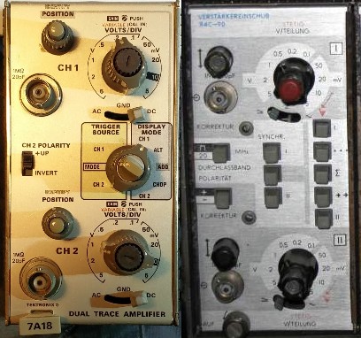
They have a lot in common. Where Tek have used rotary switches for the trigger source and display mode, and a slide switch for the channel 2 polarity, the USSR used pushbuttons for those functions. In addition, the Я4C-90 has a 20MHz bandwidth limiting switch, like the (200MHz bandwidth) Tektronix 7A26.

I’ve cut-and-pasted sections from each of their technical documentation in order to be able to compare the designs. Let’s start at the front end: the attenuator.

Attenuator

tek7a18-attenuator

First, Tektronix. They have used x100, x10, x4 and x2 attenuators with switches arranged to bring them in to circuit for the various deflection settings, from 5mV/div to 5V/div.

r4c90-attenuator

Now the USSR. They have used x100, x10, x4 and x2 attenuators with switches arranged…oh, hang on, it’s exactly the same. Even the switch combinations are the same. And whoever drew the diagram had exactly the same idea as the Tektronix drawing office when it came to representing the switching.

Well, let’s move on to the main amplifier.

Amplifier

tek7a18amplifier

Tektronix have used a FET input stage followed by a couple of bipolar differential gain stages, with an emitter follower on the output. And the USSR? Well, the input stage is visible on the right hand side of the attenuator diagram, and it’s practically identical to the Tek one even down to some of the resistor values. They didn’t have Tek’s matched dual FETs so had to make do with two individual ones matched on test. Let’s look at the rest of the stages.

r4c90-amplifier

Oh look! Two differential bipolar gain stages, just like Tek. I can only see two noteworthy differences: the gain control acts after the second stage rather than after the first, and the USSR version doesn’t have the emitter follower on the output.

Next comes the channel switch, which selects between channel 1 and channel 2 to feed to the mainframe.

Channel switch

tek7a18-channelswitch

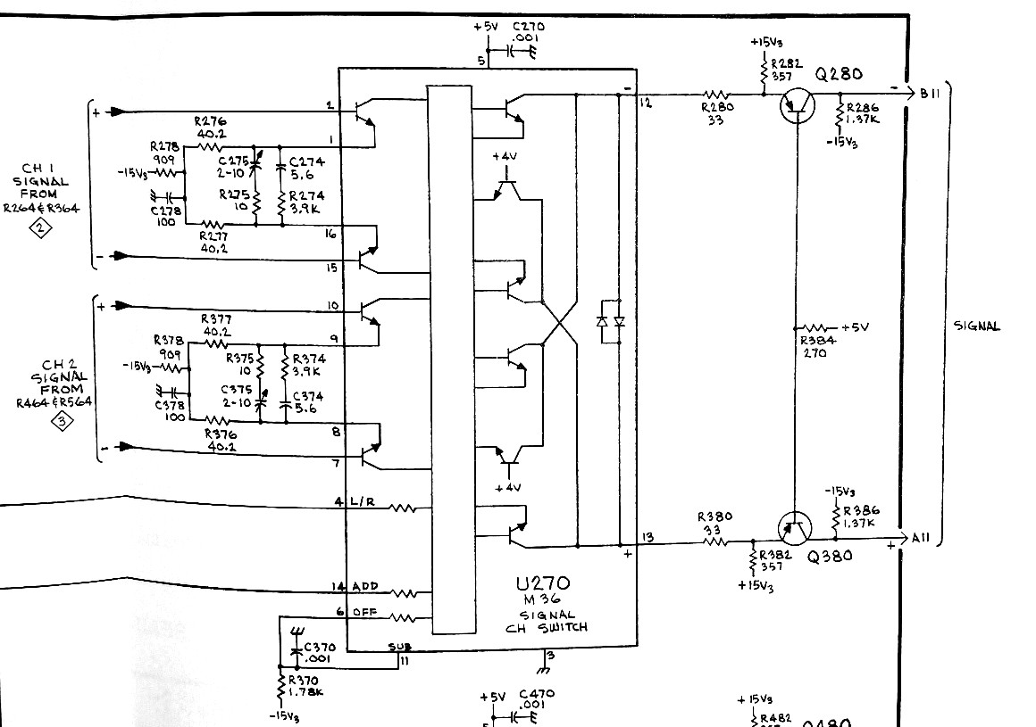
To get high performance here, Tektronix actually designed and made their own ICs. The channel switch, U270 in the diagram, uses a 155-0022, which appears in all sorts of places in Tek equipment where switching or addition of differential signals is needed. That’s followed by a transistor stage, Q280/Q380, which drives the mainframe. Here’s the soviet equivalent.

r4c90-channelswitch

Fancy that. There’s a special module, MC1, which does the switching. An internal circuit diagram  is also present, which looks suspiciously similar to the rather ambiguous diagram of the Tek 155-0022 chip. The soviet module is actually a 04КН009, which has been extensively reverse engineered by Erik Baigar, see his site here. Interestingly it’s a hybrid module rather than an integrated circuit, though it clearly does the same job.

Interesting here is the frequency compensation network. The Tek design has, between pins 1 and 16 of U270, a couple of RC networks, with one adjustment to get the high-frequency response of the stage right. Conventional enough.

The USSR design has a whole load more stuff in the same position, between pins 1 and 14 of MC1. In addition to three RC time constants with three adjustments (!) there’s a curious arrangement involving a thermistor R4 and a pair of varicap diodes D1 and D2, which seems to do some temperature-sensitive frequency response adjustment. It could be very creative design, but it smacks of desperation to me: the 04КН009 module is probably more sensitive to temperature variations than the Tek chip.

Bandwidth limiting

The final transistor stage before the output isn’t shown on the USSR diagram. It has a separate page to itself. It’s a little more complex than the Tektronix 7A18 because it has the 20MHz bandwidth limiting function. Now, there’s a Tek plugin, the 7A26, which has a 20MHz bandwidth limiting function. Just for fun, let’s look at the circuit diagram of its output stage.

tek7a26-bandwidthswitch

It has an extra pair of transistors and some filter components (C860/L860/L880) connected by a diode switching arrangement. What did the USSR do?

r4c90-bandwidthswitch

Well I never! An extra pair of transistors and some filter components (C34/L1/L2) connected by a diode switching arrangement. Great minds think alike.

There are differences, of course. The ones I’ve noticed are:

  • The Я4C-90 doesn’t have the probe identification ring and ‘Identify’ button that the 7A18 has.
  • The readout is implemented differently in the Я4C-90. It uses a 6-bit digital interface to the mainframe rather than Tektronix’s delightfully eccentric 2-dimensional analogue readout interface.
  • The Я4C-90 appears to use TTL logic to do the channel switching for CHOP and ALT modes, whereas the 7A18 uses a mechanical switch.

The architecture of the Я4C-90 is, barring minor details, identical to the 7A18. It’s close enough for me to say that it’s a straight copy which has been adjusted to suit the soviet semiconductor technology available at that time. If imitation is the sincerest form of flattery, the engineers in the USSR must have been big fans of Tektronix.

Soviet Tektronix 7000-series oscilloscope copies

Back in 1970, Tektronix introduced their ‘7000’ series of oscilloscopes. Their clever plug-in architecture offered unmatched performance and flexibility, and they quickly became an industry standard. They were ubiquitous in well-heeled electronics labs in the 1970s, 1980s and into the 1990s, at least in the US and UK. I’ve still got three examples in regular use because they do things that modern scopes struggle with. You want 10 microvolts/division sensitivity? Grab a 7A22 plugin. Want to see the same signal in the time and frequency domains together? No need to go and buy a shiny new ‘Mixed Signal Oscilloscope’. Just plug in a 7L12 spectrum analyzer. Need a 100MHz differential amplifier that can deal with 500V common-mode? No problem: Use the 7A13 plugin. All this stuff is more than 40 years old but still does a state-of-the-art job.

Behind the iron curtain, things developed at their own pace. In 1977, the Lithuanian ‘555’ factory produced the C1-91, and then the C1-115 and C1-122 ‘universal oscilloscopes’. On the right, here’s a picture I found on the web of a C1-115, together with, on the left, a picture of my own Tektronix 7603 taken a few minutes ago.

7603-c1-115Notice any resemblance? Same panel layout, same arrangement of plugins – even most of the knobs are in the same places. Let’s just say the soviet design seems to have been heavily inspired by the Tektronix one.

The soviet scopes don’t appear to have been as common in the east as the Tektronix ones were in the west, but there are some survivors in private hands. There’s a page describing the range on the TekWiki here, which includes links to some owners’ pages. However, there has been very little technical documentation available, and I’m fascinated by the technology: how much of it was copied, and how much was original?

Whilst looking for something else on allegro.pl recently, I came across a set of manuals for the C1-112 mainframe with Я4C-90 Y amplifiers, Я4C-91 timebase and 2K11 calibration plugin. They include circuit diagrams and other technical information. Bidding wasn’t exactly fierce and I got the lot for 5zł. The nice thing about them is that they’re in German, which is easier for a western audience to understand than Russian or even Lithuanian. Sadly they’re not quite the works of art that the Tektronix manuals are, but these even include the calibration certificates!

I’m very curious about what’s inside. In a future blog post, I hope to compare the Tektronix and soviet designs side-by-side and see what they have in common.

Super Breakout to JAMMA, Part 2: Colour

Having got the power supply working for my original 1978-vintage Atari Super Breakout PCB, it was time to get the screen looking right.

super-breakout-cabinet

At the time Super Breakout was made, video games were mostly black and white. Colour screens were expensive, and so were the relatively complex electronics needed to generate a colour image. But black and white images don’t look too pretty in an arcade, so colour was added by sticking patches of various colours of clear plastic foil on to the screen. Simple, and pretty cheesy, but effective enough to get more coins into the machine. Games like Space Invaders used the same technique.

Fast forward to the 21st century, however, and black and white screens have become rare and expensive while colour screens are standard. My arcade game testing and playing rig uses a colour screen, and I didn’t want to stick coloured plastic on it – it would make other games look very odd! I wondered: how about adding colour to the image electronically?

I had recently been given a MachXO2 pico dev kit from Lattice Semiconductor. It’s a neat little thing, with a 1200-LUT MachXO2 CPLD on it and a built-in USB interface which makes it easy to program. The Lattice Diamond development software is available to download and license at no cost. I wanted to gain experience using this series of chips, since they seem to offer much better price/performance than the older Xilinx CPLDs I’ve used on several projects. Colourising Super Breakout seemed like a neat and vaguely useful example project.

Super Breakout produces a roughly NTSC-standard composite video signal. It’s thoroughly analogue, and there’s no way it could be connected straight to the CPLD. My task was to convert the composite signal into separate sync and video signals, which could then be processed using the CPLD.

atari-monochrome-video-recovery

The industry-standard LM1881 chip separates the sync from the signal. Its output on pin 1 is directly compatible with the CPLD. Getting the video information is a bit more tricky. The video output from the Super Breakout board is about 0.7V peak-to-peak, which isn’t enough to reliably drive any kind of logic gate. I took the easy way out and used an LT1252 video amplifier with a gain of just under 5 to generate a signal large enough to feed into a 74HC132 Schmitt trigger which produces a clean logic output. It was also necessary to add a clamp, the transistor in the top right driven from the blanking output of the LM1881, which forces the black level of the video to a known voltage. Without the clamp, the definitions of ‘white’ and ‘black’ would drift around depending on the picture content, which leads to peculiar black patches and streaks in bright areas of the image.

The resulting waveforms look like this. At the top, the composite video waveform from the Super Breakout PCB. In the centre,  the sync pulse at pin 1 of the LM1881 chip. At the bottom, the digital video ready to feed to the CPLD.

Here’s the circuit built on matrix board, next to the Lattice development board. There’s some more electronics at the bottom left, but more about that in another post.

img_20170215_215403

Generating the colour signal was relatively simple: a counter, clocked at about 6MHz, reset by the horizontal sync signal, indicates the position along each line of video. Some comparisons of that counter with fixed values decide what colour the output should be. A simple AND function of the colour with the video input and – lo and behold – a coloured screen! And no plastic film in sight.

img_20170215_215256