One product I work on has a built-in data logger. This helps us a lot if a problem occurs: we can see the history of any faults. Every log entry is time stamped, which is important. We need to know when it’s been used and how often. However, good timekeeping is a challenge. The product has no Internet connection, it gets stored and moved around a lot, and it’s nobody’s job to check or adjust its clock, so there’s a real problem with clock accuracy.
The real time clock is based on the Microchip MCP7940N chip. The chip uses a standard 32.768kHz crystal for its timekeeping. These crystals are fickle beasts, partly because of the very low-power oscillator in the chip. The oscillator frequency, which is critical for accurate timekeeping, is very dependent on the load capacitance, which itself can vary with different builds of the PCB. The heat of soldering during manufacture also affects the crystal. I’ve seen plenty which have failed altogether, and others whose frequency has shifted significantly. Note the soldering on the crystal’s load capacitors C9 and C10 in the photo below, part of an attempt to find the optimum load capacitance on a prototype board.

All of these issues mean that just assembling the PCB and hoping for the best doesn’t work well. The frequency of an apparently working crystal can be anything up to 100ppm (parts per million) wrong. That doesn’t sound like much, but it works out to nearly an hour’s error per year, which is pretty bad.
Fortunately the MCP7940N has a neat feature which helps a lot. One of its registers, called CAL, holds a value which speeds up or slows down the clock by a small amount, like the regulator on a mechanical clock. But how do we know what the error is, and whether it’s been successfully corrected?
The MCP7940N also has a pin which can output a 1Hz square wave derived from the oscillator. With a sufficiently accurate timer, it’s possible to measure the error in the crystal’s frequency this way.
Checking the correction is more difficult. Because the chip only works on whole oscillator clock cycles, it does the adjustment to the clock’s speed by adding or removing a few clock cycles each minute. It’s therefore necessary to measure the period of exactly 60 of the chip’s seconds to find out how long its minute is, and therefore how accurate the whole clock is.
Getting a sufficiently accurate timer is the first problem. My aim was to get the MCP7940N to be accurate to within 1ppm, or about 30 seconds per year. A useful rule of thumb in metrology is that the measuring instrument needs to be ten times more precise that the quantity being measured, so we need a timer accurate to 0.1ppm, or one part in ten million. To the rescue comes my trusty Hewlett Packard 5335A universal counter. It’s an oldie but a goodie. Mine is fitted with the optional oven-controlled crystal oscillator, an HP 10544A. I checked it and set it up against a Rubidium frequency standard about 8 years ago and it hasn’t been touched since. I checked it this month against the same frequency standard, and it still agrees to within 0.1ppm. Not bad, and certainly good enough for this job.
Measuring the initial clock error is easy enough: connect the counter to the MCP7940N’s 1Hz output and look at the error. The 5335A counter has handy built-in maths functions to make this easier, so it will directly display the difference between its idea of a second and the chip’s attempt.
To measure the corrected clock output over a minute needs a bit more trickery. The 5335A counter has an external ‘arm’ input, and can average a period reading over the length of the ‘arm’ signal. All that’s needed is to arm the counter for 60 seconds and the counter will do the rest. I couldn’t find a way to make the counter do this for itself, so I cheated and used a spare Arduino mini that happened to be lying around. All it had to do was wait for a clock pulse on a GPIO pin, take another GPIO pin high to arm the counter, count 60 clock pulses, then take the arm signal low. Simple.
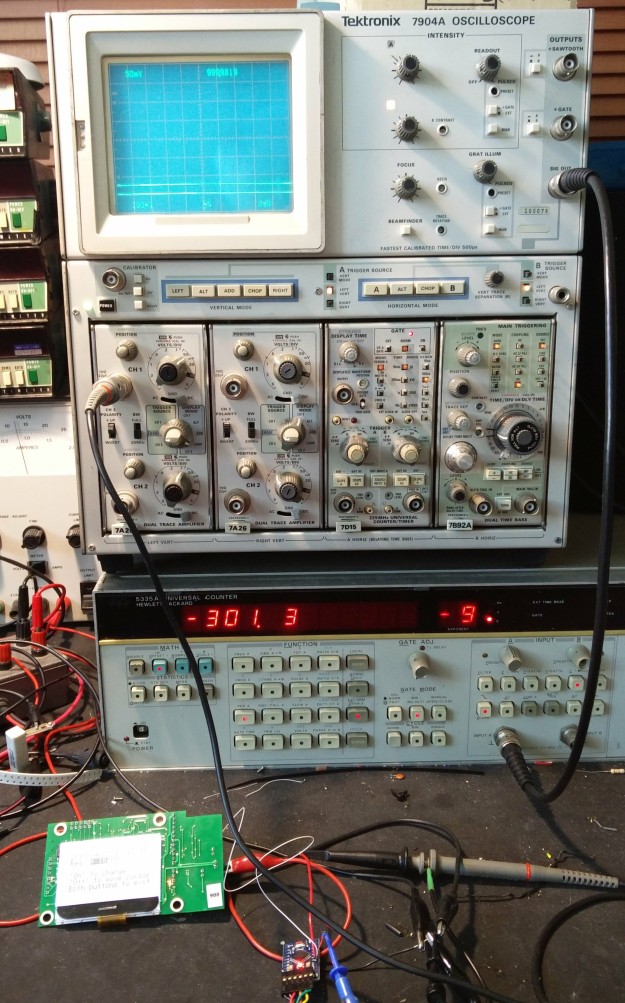
The test setup looked like this. The scope is there for ease of probing (note the cable from its ‘sig out’ connector to the counter) and it also includes a Tektronix 7D15 timer/counter module connected to the chip’s output. The 7D15 is a lot less accurate (about 1ppm) than the 5335A but it’s good enough to give an idea of what correction is required. The Arduino mini is just about visible at the bottom of the photo.

Here’s a closeup of the scope screen, showing the measured period of the clock’s 1Hz output, 999.9818ms. That’s just over 18ppm too fast.

This the setup screen of the product, showing the 18ppm correction applied to the MCP7940N’s CAL register.

Finally the error in the measured minute, calculated by the 5335A counter gated by the Arduino.

It’s showing that the corrected minute is 301.3 parts per billion, so 0.3ppm, too fast. That’s as good as it’s going to get – about 10 seconds per year. With the clock set up using this process, it has a fighting chance of staying accurate in the real world.