For the last couple of years, my wife has been using a Wileyfox Swift phone. For a budget smartphone, it’s had a few niggles but has generally been very good. A few weeks ago we and the phone got caught in an almighty rainstorm and the phone got wet. Leaving it to dry overnight didn’t help: it just made a funny fizzing noise when we put the battery back in.
I took it apart and discovered that water had got trapped in various places, not least the internal connectors to the display, cameras and so on. Some tracks on the display ribbon had completely corroded away overnight! Lesson one: if a phone gets wet, take it apart to dry it out properly. Don’t wait and see what happens.

I dried out everything else with warm air and tried the phone again. It seemed to work, giving a little vibrate when I switched it on and showing the charging LED correctly. But there was nothing on the screen. Since the damage to the display connector was plain to see and nothing else seemed to be wrong, I thought I’d try changing the screen.
A replacement screen was only £25 from a Chinese supplier on eBay. It arrived quickly, very well packed with a dinky little bag of tools too, but absolutely no instructions. I couldn’t find any on the web, either. Lots of stories about Wileyfox’s screen replacement policy, but no description from anyone who’d actually done it. Well, here’s how I did it. Or, more precisely, how I’d do it again next time – I did the dismantling in the wrong order which made it unnecessarily difficult. Many of these photos were actually taken while I was reassembling the phone.
First, unclip the back of the phone in the usual way as if to change the battery or SIM card.
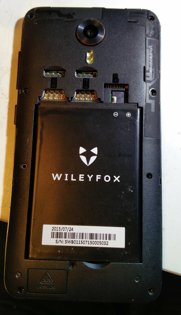
Take out the battery and undo all the little screws which hold the inner case on. I think there are nine of them and one of them is behind a sealing sticker. Use a spudger or fingernail to gently unclip the inner case from the phone’s frame, and the insides will be revealed. Notice here the red spotty sticker – a tell-tale that the phone has been wet.

This much dismantling is enough to see whether the phone will work with the new screen. The screen connector is at the top left, labelled ‘BY’ in the photo. Flip up the brown tab with a fingernail and the flexible PCB will come out. It’s easy enough, though a bit fiddly, to plug in the replacement screen, wedge the battery in place and switch on.

Joy! It works. The repair is worth continuing with. Now, remove the battery and gently unclip the black plastic assembly at the bottom right.

The whole phone is a miracle of industrial design and packaging, but the way the display is fitted is kind of awkward. It has a flex PCB which goes all the way from the bottom of the display up the inside of the phone to the motherboard connector, and runs behind the big identification sticker. Even more odd is the arrangement in the bottom left hand corner: a chip which I believe is the touchscreen controller sticks up on a bit of flex PCB through a hole in the phone’s frame, folds back on itself and has another connector which connects it to another part of the display flex PCB, so the whole thing forms a kind of knot around the frame.
To remove the screen successfully, it’s easiest to remove the motherboard first. There are various connectors to remove:
- display connector at top left, if you haven’t already done it
- selfie camera connector also at top left (flip up the black tab)
- another connector with a white flip-up tab by the SIM sockets
Remove the two screws holding the PCB and gently unclip it – it has clips on the left and right edges. Now there are two connectors to remove from the underside of the board:
- tiny ribbon plug which goes to the USB socket. This will probably just drop off itself, but it’s really fiddly to put back.
- U.FL-type antenna connector on the right hand size. Carefully prise it off with fingernails or tweezers.
The vibrator motor is attached by soldered connections on another flex PCB. I left it attached, but it might be possible to unclip it from the frame or desolder the connections. Be careful, it’s fragile.

Note how the screen flex PCB goes underneath the sticker. It turns out that it also runs underneath the USB flex PCB. Peel off the sticker (a bit of gentle heat helps to soften the glue) and peel back the USB flex PCB. I had to score the screening tape between the two flexes.

Now the screen flex PCB is free all the way to its hole through the frame near the bottom of the sticker.
Now to untangle the fiddly bit at the bottom left. First, unplug the little connector by easing up the black tab. Mine also had a bit of yellow Kapton tape holding it down. Withdraw the flex PCB from the connector and straighten out the folded flex PCB with the chip and connector on it – it’s held in place by sitting on a little peg on the frame.

Now the screen is fully disconnected. Time to remove it from the front of the phone.
The screen is bonded to the Gorilla Glass sheet which forms the front face and touchscreen. This in turn is just stuck to the phone’s frame with double-sided tape. I used a heat gun to warm the glass and soften the adhesive, and a combination of a Stanley knife and spudger to ease it away from the frame. The glass is surprisingly strong and flexible: I managed not to break it.


Once the tape has all softened and come off, the screen’s flex PCBs should come free with a bit of wriggling. Now clean off the self-adhesive goo. I used a spudger and car brake cleaner for this. The surfaces of the frame should be clean and smooth ready to accept the new screen.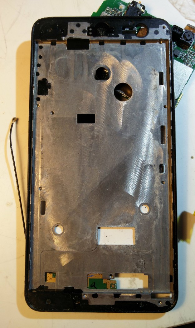
The new screen needs a bit of preparation before fitting. The little connector for the touchscreen has to be disconnected:

and it needs some self-adhesive tape applying, because it doesn’t appear to come supplied with any. I used little bits of carpet tape (!), shown in the photo below still with its yellow backing paper on.

Now thread the screen’s flex PCBs through the holes in the frame where they should fit, being particularly careful with the folding chip thingy, and the touchscreen ribbon which is easy to get trapped and forget about. Once you’re happy that the flex PCBs are sitting in the right places, peel off the backing from your double-sided tape with a scalpel or tweezers and stick the screen in place.
Assembly is the reverse of disassembly, to coin a phrase.
Dress the flex PCBs into their final positions. Fold up the touchscreen chip and connector and pop it on to its little peg, then plug in its ribbon and lock the connector. Then lay the flex PCB to the motherboard in place, lay the USB flex PCB on top of it and re-stick the Wileyfox sticker. Don’t get cat hair on the back of the sticker because it won’t stick properly.
Put the motherboard back in, taking care to reconnect all the cables including the really fiddly one to the USB flex PCB. I found I had to manipulate it with the blade of a knife underneath the motherboard. Once the screen is reconnected, it’s time to switch on for a test.

Success! Now just to put the screws back in and celebrate. The phone works again, though the rear-facing camera appears to have died. I don’t know if that’s because of the water or because I dislodged its connector and didn’t notice. One day I’ll have another look at it. Until then, this phone is now only a spare, so nobody’s too bothered about not being able to take photos with it.


Thanks for that, very useful. A few notes to add:
On the connector by the SIM sockets it’s the dark tab on the opposite side to the ribbon cable which flips up. Don’t try to flip up the white bit – you’ll break it.
I found that the easing the vibrator motor out of the frame was very straightforward – it’s mounted in a rubber tube.
My situation was a little different as I had cracked glass so the replacement was a combined glass/screen combo which was already bonded. The gorilla glass, once cracked, is extremely brittle and will splinter easily. Work carefully, making sure you get all of the old glass and bond out and WEAR EYE PROTECTION.
At the time of writing, the kit I got is still available (from Ocolor via Amazon), and it included all of the required tools (cheap and cheerful but sufficient) and the double-sided tape
Glad the article was useful to you, and thank you for the notes. I’m sure they’ll help other readers. My replacement screen was also pre-bonded to the glass.
Thanks for writing this guide!
I’m struggling with almost the first step of the instructions; once I’ve unscrewed the inner case, I can’t detach it from the frame. I can get my fingernails under the edge around the inside of the battery compartment, but around the outside of the frame I can’t get any purchase at all. Is there something I’m missing?
Thanks!
I remember that was a fiddly part. I think there are clips all the way around the edge. One or two of them were already broken on this phone from general use and being dropped, which provided me with a way in to start unclipping them. I remember it being difficult to keep some clips unclipped while attending to the others, because the case tended to spring back in to place. Start in the middle of one of the long edges where it’s a bit more flexible.
Bit late for you, Alex, but might help someone else: I’ve been having exactly this problem, and it turned out that I was trying to separate the wrong pieces of plastic. Look at the volume rocker: it’s right next to a silver band that runs all the way round the edge of the phone. This band is a part of the inner case that you’re trying to remove, despite how it looks.
It looks like the inner case meets the battery-facing side of that band and is a very tight fit, but in fact they’re both the same piece of plastic. Try getting your fingernail on the front side of the band instead, between it and what seems to be the screen (but isn’t) and you should find it much easier.
I followed Martin’s suggestion, starting on the long edge opposite the volume rocker, and it took about a minute to get the whole inner case off with my thumbnail. Before then, I’d been trying for quarter of an hour to find any gap, even with a blade, and had made no progress at all.
Thank you very much!!!! My first DIY phone repair and because of this blog it went great 🙂
I’m glad to hear it was useful – thanks for the feedback!
This was immensely useful, thanks Martin. I had bought a screen with frame, which I was really grateful for, because my glass screen (despite having a Gorilla glass protector pasted onto it) was smashed in literally thousands of pieces, and it would have been really difficult to get it all off. However, that meant that some parts of your disassembly process were different for me. For one, there is a small piece glued to the side of the metal part of the screen, which connects the buttons. I had to use a heater to peal it off my broken screen and paste it to the new screen (as it come without one).
However, there is a big HOWEVER here: since putting everything back into place, the speaker stopped working and it’s not charging via USB anymore. I have dis- and reassembled it a couple of times already and cannot figure out what I’ve done wrong. There was some adhesive tape on the back of the bottom left fiddly bit (ha! :D) that I had forgotten and now removed. Didn’t fix it. Also, the yellow flexible circuit board underneath the metal frame looks different than the old one… fewer connections. Might that be the issue? Any help is really appreciated here. 🙂
Thank you for the feedback – I’m glad the article was useful, and the detail differences in your phone are good to note. I can’t remember how the speaker is connected, but the USB charging problem sounds like it’s worth re-checking that the flex connector on the USB board at the bottom and its other end on the motherboard are seated properly. I had a problem with the camera not working, and that was just because I hadn’t seated its connector properly. Using a magnifier to examine them helps, I find. Good luck!
Again, much appreciated Martin. 🙂 I did reopen my phone a couple of times to check whether I had put everything back in place properly and didn’t fudge any connections. Simply by looking at the circuits I couldn’t really tell which parts to connect. Any chance you could indicate what I should be looking at? Using a magnifier is a good idea! If only I had one, though… ;]
That worked a treat, thank you so much! My phone looks brand new now, and you probably saved me a few hours of looking for these steps by myself. I would add a few gotchas regarding re-assembly: There’s 4 connectors on the motherboard, you don’t want to miss any. Among them in particular, the USB flex connector in the back should be plugged in before sticking back the barcode label, for easiness.