The recent demise of my old workshop PC has spurred me into action. Back in the halcyon days of the late 90s and early 2000s, I used to DJ a bit. I was an early adopter of computer-based DJ technology. In those days it was still fairly unusual to have music in MP3 format – the iPod wasn’t released until late 2001 – never mind being able to actually DJ with it. At the time I found a product from a German company which did exactly what I wanted: it was a combination of hardware and software called BPM Studio which meant I could use MP3 files as if they were a professional CD player: cueing them, pitch-shifting, mixing and so on. The hardware is a solidly-built control panel which connects to the PC, on which runs some software which does all the audio processing.
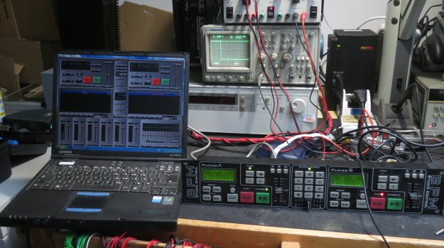
So why has the failure of my old workshop machine reminded me of this? Because, once upon a time, it was my media PC, and it ran the DJ software. The software and hardware is now 15 years old, and it shows: the controller connects using a serial port (when did you last see a PC with one of those?) and the software has…wait for it…a dongle! Yes, just like in the bad old days, it has a device which plugs into the parallel port on the PC, and if it’s not found, the software won’t run. Parallel ports, especially, are a dying breed today, so the chances of being able to use this controller and software in the future fade as PC technology moves on.
The BPM Studio package was expensive, and the controller is quite nice and robustly built, so I’d like to be able to preserve it and, if possible, use it with more modern software. The trouble is, its interface to the PC is proprietary, unsupported by any other software, and I couldn’t find any documentation on it. There was only one way forward to protect my investment: hack it.
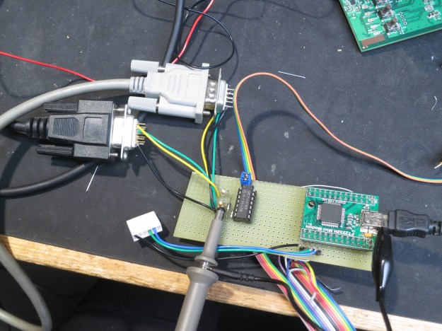
The first step was to have a look at what was going on on the serial connection, and what baud rate was in use. I put a little breakout adapter in the serial cable (this one, in fact, modified a bit) so I could examine the data.
First thing was to figure out the baud rate. Set the scope to trigger on the rising edge and play with the timebase a bit and soon we can see the start bit of each byte:
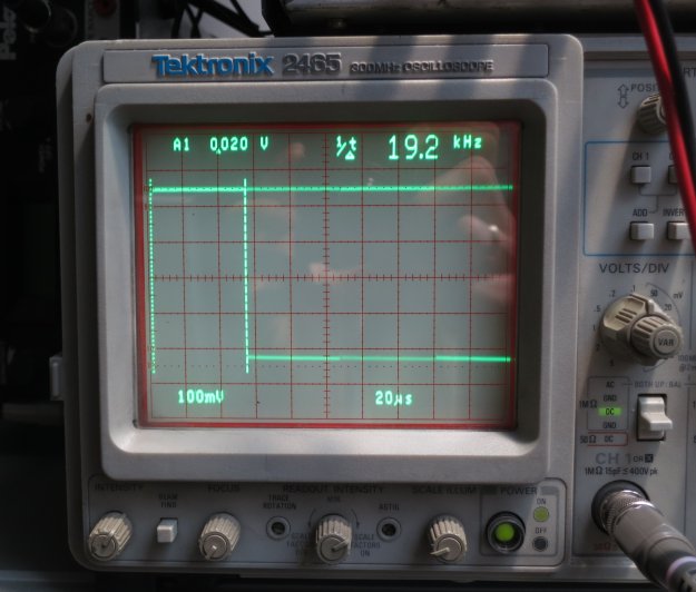
That’s definitely 19200 baud. Nice and standard. So I started my handy hdump2 software, which displays two streams of data side by side so it’s possible to see what came from where and when, and hoped to see something which made sense: a recognisable packet format, perhaps, or at least consistent data. What I got instead was this:
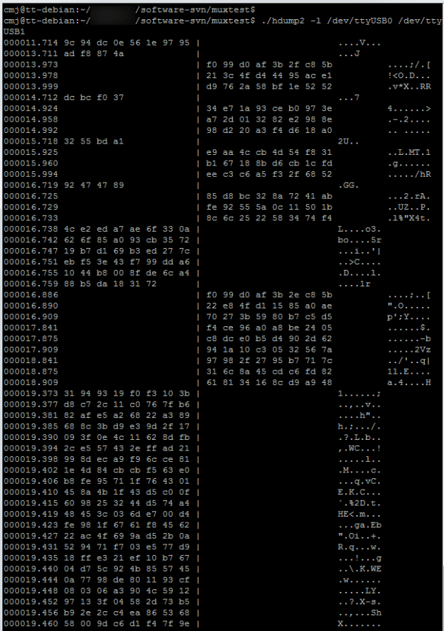
The left column is data from the PC, and the right column is data from the controller. It’s clear there’s a conversation going on, but it looks encrypted to me. There are no obvious packets, no start or end markers, nothing clearly related to what’s going on. I played around pressing buttons on both the controller and PC, and lots of data flowed but nothing made any sense. No readable track names for the displays, no recognisably similar data when I pressed the same button numerous times.
Why on earth would anyone encrypt the connection between the PC and a controller like this? Only the designers know, but I guess it’s part of the same mindset that required a hardware dongle to run the software. A fear of piracy, probably.
Interestingly, if the PC and controller are separated, they each send out a burst of data once a second. The PC sends bursts of 4 bytes, and the controller sends bursts of 12 bytes. Each of them follows a fixed pattern from startup. The PC sends:
9c 94 dc 0e
56 1e 97 95
ad f8 87 4a
dc bc f0 37
32 44 bd a1
and so on. The controller sends:
f0 99 d0 af 3b 2f c8 5b 21 3c 4f d4
44 95 ac e1 d9 76 2a 58 bf 1e 52 52
34 e7 1a 93 ce b1 97 3e a4 f9 01 37
d3 f3 94 c1 32 57 31 a7 9a 6c 83 68
84 ae d1 f6 e7 c1 c8 5d e2 e4 46 36
and so on. I can’t see an obvious relationship between them. What I can see from the conversation dump above is that the controller seems to restart its sequence when it sees the data from the PC, but with some subtle differences.
If I was a proper mathematician, I’d spend more time trying to work out what the code was. Being an engineer, I thought I’d take it apart and have a look inside.
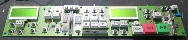
There’s more to it than I thought. This predates the days of powerful PIC and AVR microcontrollers, and actually has separate chips for its CPU, ROM and RAM. That’s good news for anyone interested in reverse engineering it. The CPU is a Siemens/Infineon 80C166:
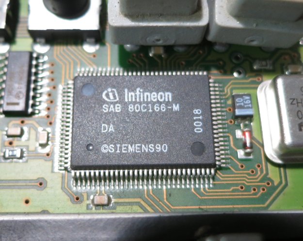
and there’s a 29F010 (128 KByte) ROM connected to it, presumably holding the software:
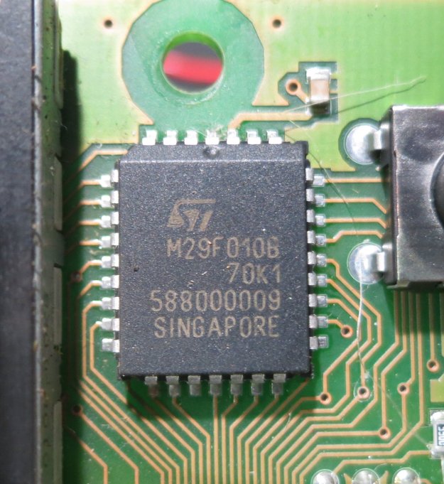
There’s also a 32K RAM chip, which is more than I’d expect. I just hope the software isn’t doing something horrible like decrypting itself into RAM and running from there.
The good news is that documentation for the 80C166 is freely available, as is a disassembler, ADIS16X. And I’ve just ordered a PLCC32 adapter so that the ROM, once I’ve desoldered it, will fit my EPROM programmer. Watch this space.
