I do a lot of electronics design and debugging. It’s how I make my living. Most of the things I work on involve embedded computers of one sort or another talking to various peripherals. It could be an 8-bit microcontroller sending data to a simple data logger, or a sophisticated 32-bit Linux system communicating with a wireless modem. Many of these connections involve asynchronous serial ports. If something goes wrong, as it usually does, It’s really useful to be able to see what’s going on with the communications. Here’s a picture of the sort of thing I’m dealing with. It’s a board I designed which contains a load of power electronics as well as a microcontroller and a USB data logger which talk to each other using a serial connection. Note the 175A fuse next to the USB connector!
Monitoring a serial port on a PC is relatively easy, but the ones I deal with are separate from the PC, stuck on some circuit board on the workbench or buried inside a piece of equipment. To complicate matters, I need to monitor both directions of traffic at the same time, and have some idea of what order things happened in. There are many protocol analyser tools out there which will do all sorts of clever things, but it’s hard to justify them for small projects.
Faced with a such problem to solve recently, I put together a cheap and simple system which allows a developer to monitor both directions of an embedded serial port simultaneously, and have a record of which end transmitted what, when. It consists of a software tool and a bit of hardware.
Software
The software is a simple tool I wrote in C. It compiles and runs under Linux. Given the names of two devices, it opens both of them. It waits for a character on either of them and displays it on the screen in hexadecimal and ASCII. Each device has a separate column. Every time data arrives from the other device, it starts a new line. Each line is timestamped. In this way, it produces a dump of the conversation between the two devices, and it’s clear what order things happened in, and who said what.
It has one other handy feature: it has a ‘-l’ for (‘live’) command line option. In this mode, it will update the display every time a character arrives so you can see occasional data as it happens. This is great for monitoring things like keystrokes. This mode involves a whole load of backspacing and overprinting on the display, so it’s not really suitable if you want to record the output of the tool for later examination. The non-live mode is better for that – it outputs data only when it has a complete line.
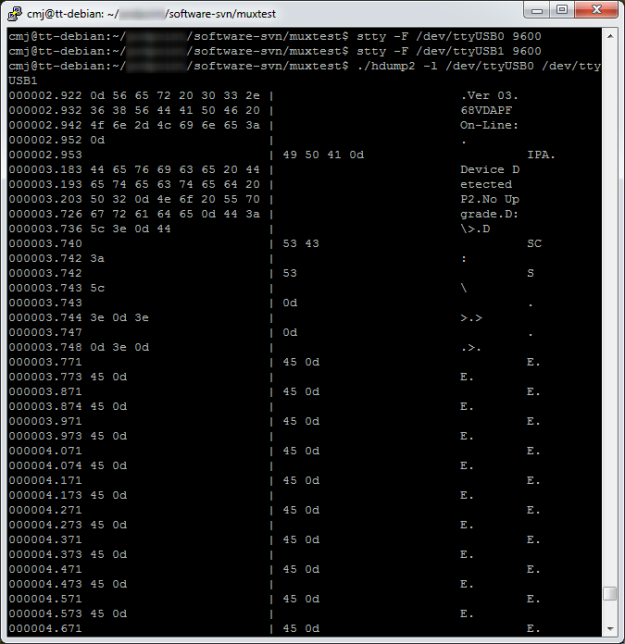
Here’s an example session using the software.
 Here you can see that I used stty to set the baud rate of two serial devices attached to the PC. Then I ran the tool (provisionally called hdump2). You can see the data after that. The timestamps are on the left, followed by hexadecimal representations of the data, then the ASCII version. In this case we’re watching the initialisation of a Vinculum USB host controller. The data isn’t guaranteed to be in exactly the right order character-for-character, since it’s had to travel from two serial ports through the operating system, but it’s good enough for debugging.
The source is available to download here:
To build it:
tar xzf hdump2-1.0-source.tar.gz
make
It’s free software, licensed under the GNU General Public License.
Hardware
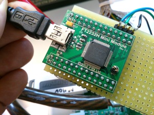
The hardware can be any pair of serial ports suitable to connect to the device under test, but I made a little module which makes it easier. It’s based on an FTDI FT2232H Mini Module. In fact, that’s all it is! There are just a couple of wire links to configure its power supplies and bring the receive pin of each of its two serial ports out to a connector. There’s a load of spare space on my board which I intend to use eventually to fit various useful connectors and buffers to hook up to the different serial port standards I come across.
The wiring looks like this:
- Join pin CN3-1 to CN3-3
- Join pin CN2-1 to CN2-11 and CN3-12
- serial input 1 is on CN2-10
- serial input 2 is on CN3-25
- input ground is on CN3-2 and CN3-4
When plugged in to a PC, two devices (typically /dev/ttyUSB0 and /dev/ttyUSB1, assuming you don’t have any other USB serial ports attached) appear. They can be used as the device arguments to the tool.
Do let me know if any of this is useful to you, or if you have comments or improvements to suggest or contribute.


Pingback: Arduino a Altera CPLD | 3.2.1…….
Pingback: Lattice FPGA programming adapter from the junk box | martinjonestechnology
Pingback: Cracking the code: reverse engineering the AlcaTech BPM Studio controller | martinjonestechnology