Tag Archives: analogue

Sony WM-D6C Walkman Pro DC-DC converter repair

This story starts with the long drive from Cambridge, UK to Warsaw, Poland. I like to be able to listen to music to while away the hours in the car, and I decided to use cassettes. Why? Our car radio is faulty, so much of the time there’s hardly anything to listen to. It has a CD player, but almost all of my CDs are stored away, having long since been converted to MP3s. There’s a handy AUX IN jack, so I can plug in my smartphone. But there’s simply no way to operate a smartphone without looking at it, and I’m not taking my eyes off the road at Autobahn speed.

My solution? Cassettes! I’ve got lots of them, generally high quality recordings, which I’ve never digitised, so they’re not stored away. They’re easy to operate with one hand without looking at them, too. But the car has no cassette player. Sorry, had no cassette player. A little judicious eBay shopping got me a Sony WM-D6C Walkman Professional in immaculate condition for a somewhat lower-than-average price because it didn’t work.

IMG_20190101_132309

The WM-D6C is widely acknowledged to be one of the finest portable cassette machines ever made. It’s pocket-sized, if you have large pockets, and has sound quality and features that rival full-sized hi-fi cassette decks. It can also record, which is extremely unusual for a Walkman-format machine.

This particular example is a very late one. It doesn’t have the posh amorphous head of the original models, but the electronics are mostly easy-to-access surface-mount components rather than the gruesome bird’s nest of wire-ended parts that the early models had. I remember servicing an early one for a student radio station and it wasn’t a lot of fun. I think this one must have expired quite early in its life and been left on a shelf, because there’s no perceptible head wear and the casing is unmarked.

Putting batteries in and pressing play resulted in the ‘BATT’ LED coming on but absolutely nothing else. No clicks in the headphones, no motor whirring, nothing. Fortunately the service manual is readily available on line. ‘Supplement 4’, dated 2001, accurately describes my example.

Browsing the circuit diagram revealed one of the secrets of the WM-D6C’s excellent performance. Most Walkman-type cassette machines used a pair of ‘AA’ cells, so all the electronics had to run from just 3 volts. That’s common enough in 2018, but back in the day it was a real challenge, so the capabilities of the motor and electronics were compromised. The WM-D6C not only runs from four ‘AA’ cells, for a 6 volt supply, but does even better. Almost the first thing it does is step up that supply to about 11 volts. That rail then runs nearly everything, including the motor and audio circuits. A nice generous supply voltage is a good start for getting top performance, especially with 1980s-era technology.

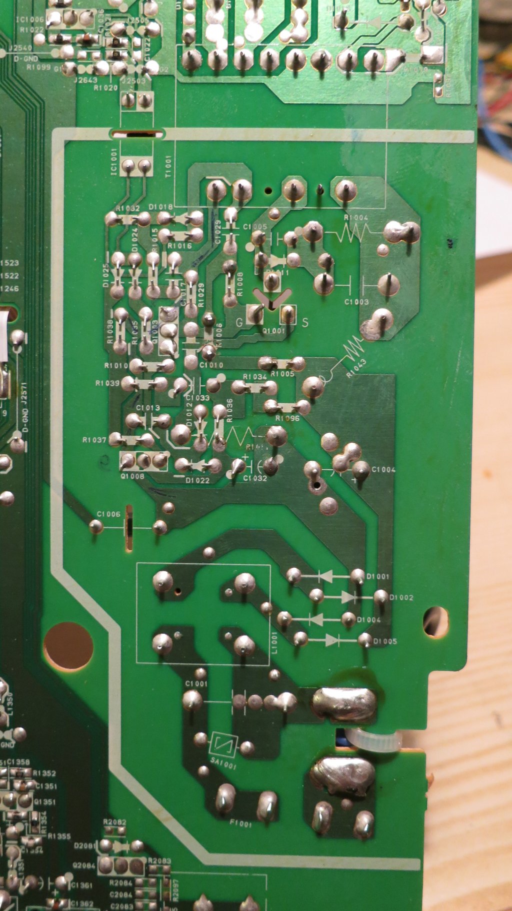
A quick prod with the multimeter revealed the problem. This boosted supply was entirely absent. Seeing as how it powers most of the machine, that would explain the lack of results. The supply rail comes from a much-feared component, the DC-DC converter (CP304). Inscrutable in its little screening can, labelled ‘SONY’ on the right hand side of the picture of the Walkman’s entrails below, it’s often considered unrepairable.

IMG_20181002_151808

The service manual includes a somewhat misleading diagram of its innards. I think the diagram is actually back-to-front, showing the output and input swapped, because that’s the only way it makes sense. The NPN transistor makes a boost converter in a variation on the classic ‘joule thief‘ circuit, and the PNP one with works with the zener diode to regulate the output by depriving the switching transistor of bias if the output voltage rises too high.

WM-D6C DC-DC converter

The converter wasn’t too hard to remove and dismantle, given reasonable desoldering tools and a powerful iron to unsolder the can. Here’s what’s inside. There are components on both sides of the board, and a certain amount of grey silicone which is easy enough to peel off. Back in the 1980s this would have seemed intimidating in its compactness, but it’s easy to work on given modern tools.

Finding the fault was a case of looking for the ‘usual suspects’: there were two tantalum bead capacitors sitting there looking guilty.  The one on the input was short-circuit, which had killed off the 22uH inductor connected to pin 3, the large green component on the right.

I replaced the faulty components, using a higher-voltage-rated tantalum and a ceramic chip in parallel to replace the capacitor, and a surface-mount inductor with bits of wire soldered on to it. The values aren’t very critical and I just used what happened to be lying around. A quick test, giving it 6V from a bench power supply, revealed a healthy 11V or so at the output.

After reinstalling the converter and reassembling the machine (watch out for the little ‘speed tune on/off’ knob at the back) it worked! It shows signs of having had attention from the phantom twiddler. The head azimuth adjustment screw was tightened up, but good quality sound returned when it was properly adjusted. The peak level meter seems rather unenthusiastic so may need adjustment, and I haven’t checked the recording bias yet. There’s also a forest of little surface-mount electrolytics waiting to dribble corrosive ooze all over the PCB, but that’s a job for the long winter evenings. For now, it’s working. Being able to play cassettes has turned out to be unexpectedly useful. We rediscovered a tape of nursery rhymes from Domowe przedszkole, a classic Polish children’s TV programme, which granted us peace on a long trip recently!

Good accuracy from a low cost Real Time Clock

One product I work on has a built-in data logger. This helps us a lot if a problem occurs: we can see the history of any faults. Every log entry is time stamped, which is important. We need to know when it’s been used and how often. However, good timekeeping is a challenge. The product has no Internet connection, it gets stored and moved around a lot, and it’s nobody’s job to check or adjust its clock, so there’s a real problem with clock accuracy.

The real time clock is based on the Microchip MCP7940N chip. The chip uses a standard 32.768kHz crystal for its timekeeping. These crystals are fickle beasts, partly because of the very low-power oscillator in the chip. The oscillator frequency, which is critical for accurate timekeeping, is very dependent on the load capacitance, which itself can vary with different builds of the PCB. The heat of soldering during manufacture also affects the crystal. I’ve seen plenty which have failed altogether, and others whose frequency has shifted significantly. Note the soldering on the crystal’s load capacitors C9 and C10 in the photo below, part of an attempt to find the optimum load capacitance on a prototype board.

img_20180530_100756

All of these issues mean that just assembling the PCB and hoping for the best doesn’t work well. The frequency of an apparently working crystal can be anything up to 100ppm (parts per million) wrong. That doesn’t sound like much, but it works out to nearly an hour’s error per year, which is pretty bad.

Fortunately the MCP7940N has a neat feature which helps a lot. One of its registers, called CAL, holds a value which speeds up or slows down the clock by a small amount, like the regulator on a mechanical clock. But how do we know what the error is, and whether it’s been successfully corrected?

The MCP7940N also has a pin which can output a 1Hz square wave derived from the oscillator. With a sufficiently accurate timer, it’s possible to measure the error in the crystal’s frequency this way.

Checking the correction is more difficult. Because the chip only works on whole oscillator clock cycles, it does the adjustment to the clock’s speed by adding or removing a few clock cycles each minute. It’s therefore necessary to measure the period of exactly 60 of the chip’s seconds to find out how long its minute is, and therefore how accurate the whole clock is.

Getting a sufficiently accurate timer is the first problem. My aim was to get the MCP7940N to be accurate to within 1ppm, or about 30 seconds per year. A useful rule of thumb in metrology is that the measuring instrument needs to be ten times more precise that the quantity being measured, so we need a timer accurate to 0.1ppm, or one part in ten million. To the rescue comes my trusty Hewlett Packard 5335A universal counter. It’s an oldie but a goodie. Mine is fitted with the optional oven-controlled crystal oscillator, an HP 10544A. I checked it and set it up against a Rubidium frequency standard about 8 years ago and it hasn’t been touched since. I checked it this month against the same frequency standard, and it still agrees to within 0.1ppm. Not bad, and certainly good enough for this job.

Measuring the initial clock error is easy enough: connect the counter to the MCP7940N’s 1Hz output and look at the error. The 5335A counter has handy built-in maths functions to make this easier, so it will directly display the difference between its idea of a second and the chip’s attempt.

To measure the corrected clock output over a minute needs a bit more trickery. The 5335A counter has an external ‘arm’ input, and can average a period reading over the length of the ‘arm’ signal. All that’s needed is to arm the counter for 60 seconds and the counter will do the rest. I couldn’t find a way to make the counter do this for itself, so I cheated and used a spare Arduino mini that happened to be lying around. All it had to do was wait for a clock pulse on a GPIO pin, take another GPIO pin high to arm the counter, count 60 clock pulses, then take the arm signal low. Simple.

The test setup looked like this. The scope is there for ease of probing (note the cable from its ‘sig out’ connector to the counter) and it also includes a Tektronix 7D15 timer/counter module connected to the chip’s output. The 7D15 is a lot less accurate (about 1ppm) than the 5335A but it’s good enough to give an idea of what correction is required. The Arduino mini is just about visible at the bottom of the photo.

img_20180427_171833

Here’s a closeup of the scope screen, showing the measured period of the clock’s 1Hz output, 999.9818ms. That’s just over 18ppm too fast.

img_20180427_171723

This the setup screen of the product, showing the 18ppm correction applied to the MCP7940N’s CAL register.

img_20180427_171715

Finally the error in the measured minute, calculated by the 5335A counter gated by the Arduino.

img_20180427_171823

It’s showing that the corrected minute is 301.3 parts per billion, so 0.3ppm, too fast. That’s as good as it’s going to get – about 10 seconds per year. With the clock set up using this process, it has a fighting chance of staying accurate in the real world.

That syncing feeling: classic arcade games that won’t stay still

I’ve got a collection of classic arcade games from the ‘golden era’ of the early 1980s. They’re not the whole wooden cabinets with flickering lights and cigarette burns, but just the circuit boards from inside. They are easy to store and easy to plug in to a joystick and monitor to play.

However, some of them have always been a bit tricky to see. The monitor I use, a spiffy Microvitec bought surplus from Display Electronics in 1990, has fantastic picture quality but is a bit fussy about its input signal. Specifically, it seems to expect that the sync pulses – the bits of the signal which indicate where lines and pictures start – must conform more-or-less closely to broadcast standards. Unfortunately, the people who designed the old video games weren’t too worried about complying with standards. The result is that, on my monitor, some games tend to flicker and roll, or require very finnicky adjustment of the controls.

There’s loads of information about what video sync pulses are supposed to look like on the web.  This link has plenty of detail. However, the important things here turned out to be that the horizontal sync pulses should be fairly close to 4.7 microseconds long, and the vertical sync pulses should be pretty much three lines, or 192 microseconds, long.

I compared the outputs of various games – one which had never given problems (Mr Do’s Castle) with three which were troublesome (Phoenix, Pleiads and Q*Bert). The results were interesting. Here’s the vertical sync period from Mr Do’s Castle:

mrdocslv

In all the scope pictures, the red trace is the sync output from the game, and the blue line is the vertical sync from my electronics which I’m just using to trigger the scope at the right time.

In this case, the narrow red pulses are the horizontal sync pulses, and the broad area between the dotted lines is the vertical sync pulse. It’s six lines, or about 386 microseconds, wide, which seems to be good enough to keep the monitor happy.

Examining Pleiads and Phoenix, which have the same video electronics, here’s the horizontal sync pulse:

pleiadsh

Oh dear, It’s only 3 microseconds wide when it ought to be 4.7. And the vertical sync pulse?

pleiadsv

It’s a full eight lines wide, or more than 500 microseconds. Those numbers are way off what the monitor is expecting. The result is that the monitor refuses to give a stable picture, which makes playing the game very tricky:

Img_7793

Looking at Q*Bert, its horizontal sync pulses are nearly three times as wide as they should be, at 12.6 microseconds:

qberth

and Q*Bert’s vertical sync pulse looks like this:

qbertf

It lasts more than a millisecond! That’s miles off. The effect on the picture looks like this:

Img_7782

That’s as stable as I could get it. Notice how the left hand side (which is actually the top – the monitor is rotated 90 degrees)  is curved and wobbly. It was fairly hard to adjust the monitor to get the picture stable enough to take a photo.

There are solutions to these problems which involve modifying the game boards themselves, but I didn’t want to do that. I think they’re interesting historical artefacts (even the bootleg ones) and I try to keep them as original as possible. I wanted to fix the sync problems outside the board.

After a bit of experimenting, I came up with a little circuit which regenerates the sync pulses to be a bit more standard.

Img_7778

Untangling the rat’s-nest of wires, the schematic diagram looks like this:

syncfix-schematic

The circuit is simple and cheap, using two standard TTL logic ICs. It ought to work with 74HC series chips as well, but some of the resistor values might need changing. The diode is any common-or-garden signal diode: a 1N4148 or 1N914 is fine. It works like this.

  • IC1B is a monostable which triggers on every sync pulse, generating a pulse 4.7 microseconds long. These become the new horizontal sync pulses.
  • IC2B combined with D1, R3 and C3 form a sync separator which triggers the monostable in IC1C only on sync pulses which are longer than about 40 microseconds.
  • IC1C is a monostable which generates vertical sync pulses about 200 microseconds long.
  • IC2E combines the new horizontal and vertical sync pulses into a new sync signal.

The output isn’t what you might call broadcast standard, but it’s close enough to make the monitor happy. I’ve tried it on a few games and it works even on games which the monitor was happy with before. Here’s the results from Pleiads:

pleiadsc

Nice horizontal sync pulses, with a vertical pulse 193 microseconds long. There are a few extra pulses around but the monitor doesn’t seem to mind.

Img_7783

The results from Q*Bert are also good, though the vertical sync looks even more odd:

qbertc

The vertical sync pulse is a sensible length, but there’s a long pause after it before the horizontal pulses start again. That doesn’t bother the monitor, though, and all the wobbles have gone away. Here’s the test setup in use.

Img_7777Sorry about the mess, but at least the display on the monitor is tidy. Mission accomplished.

Repairing a floppy disc drive

Why on earth would anyone want to repair a floppy disc drive? It’s quite a while since most of us bade them good riddance and started using USB sticks and Flash memory cards. However, I still use floppies from time to time, mostly with my trusty BBC Micro which still sits in the corner of the workshop.

Recently I was asked to recover some documents from some old 5.25″ BBC Micro floppy discs. The documents themselves were in an unusual format, about which more another time, but the first step was to simply get the data off the discs. The discs were 80-track ones, and I have a pair of Chinon FZ-506 80-track drives for the Beeb.

Img_6556

Out of all the various Beeb drives I’ve had over the years, I’ve kept these two because they’re housed in a compact casing with a mains power supply, and they have handy 40/80 track switches on the front, not hidden round the back. One drive has always been a bit reluctant to start spinning, but for occasional workshop use that wasn’t a problem. I’d got in to the habit of just opening and shutting the door a little which would kick the motor into action. However, when it came to intensive use backing up these old discs, which needed both drives, the failure to start became a real pain. I didn’t have a spare drive, and finding another one (especially in Poland) isn’t easy these days.

My curiosity got the better of me and I decided to open up the drive and find out what was wrong with it. It wasn’t hard to take apart and I soon had the motor revealed. Here’s a photo of it sliced into its component parts.

Img_6340

It’s a ‘pancake’ motor, so called because it’s (nearly) flat. The shiny silver bit on the left is the turntable which drives the disc, and it sits in a bearing. The next layer is the circuit board containing the windings and controller circuitry, and below that is the rotor which is a multi-pole magnet on a steel disc.

The motor is controlled by a Mitsubishi M51785P motor controller chip. The chip’s data sheet revealed that the motor has three phases, each of which has a coil to drive the rotor round and a hall effect sensor for feedback. This particular one is arranged with two coils per phase, but occupying 6/7 of a revolution, so the motor goes more slowly than the chip is driving it. At least, I think that’s what’s going on. Here’s a closeup of the circuit board. You can see the six coils, and the coloured wires I soldered on to measure things while the motor was running. Because of the way it’s built, it’s impossible to access most of the circuit board while the motor is assembled.

Img_6338

The controller chip seemed to be doing all the right things: its oscillator was running, and the outputs to the coils were doing sensible things. The coils themselves were all undamaged and measured the same resistance as each other. But I noticed something odd about the hall effect sensors. There are three of them, HG1, HG2 and HG3. I noticed accidentally that if I shorted together the two wires taking the output of HG1 to the controller, the motor still ran but sounded very rough. Not surprising. The same happened if I shorted the output from HG3. But shorting the output from HG2 had no effect at all. Aha! Only HG1 and HG3 seemed to be having any effect on the motor. I swapped HG1 and HG2 just to see what would happen, and the fault moved to HG1. That proved to me that I had a faulty sensor, not a faulty chip.

Where to get a replacement sensor, though? This drive was made some time in the late 1980s, and I couldn’t find hall effect sensors in today’s electronics catalogues which would fit mechanically and electrically. I had a rummage around the workshop and found a scrap 3.5″ floppy drive. A squint at the circuit board revealed a suspiciously hall-effect-looking device of the right shape and size nestled next to the spindle rotor, used for index sensing. Well, it had to be worth a try. I extracted it and fitted it to the 5.25″ drive in place of the faulty one.

Success! The motor now ran more smoothly, and shorting each of the hall sensors in turn had roughly equal effects, so they were now all working. Best of all, the motor started reliably every time. Interestingly it wasn’t as quiet as the other drive, but I suspect the scavenged hall sensor is optimised for magnetic fields from the side rather than the front, given how it was mounted, so it’s probably not perfect.

The last job was to realign the head slightly, because this drive was a bit fussy about reading some discs. I found a disc that it struggled with but that the other drive would read every time, and tweaked the position of the head stepper motor each way a little until this drive read that disc reliably. You can see in this photo that the stepper motor has elongated mounting holes, so it’s possible to loosen its screws (there’s another one just out of shot to the right) and turn the motor a few degrees to adjust the position of the head.

Img_6344

After all this work, the drive read all the discs I asked of it without any problems. I hope it’ll be OK for the next decade or two.

Denon DVD-1720 DVD player power supply schematic and repair

A couple of weeks ago, my wife and I wanted to watch a movie. I went to put the DVD in the player, and was disappointed to find that the machine was dark and didn’t respond to any of its buttons. It was broken.

Img_6385

It’s hard to say that a DVD player is really worth fixing. This one, a Denon DVD-1720, is about 7 years old, and wasn’t expensive when it was new. However, I was curious to know why it had stopped working, and that alone was reason enough to delve inside.

Considering its low cost (I think it cost about £100 when new) it was very neatly constructed. Removing a few screws allows the top to come off (careful of sharp edges) and the plastic front panel just unclips with a bit of gentle persuasion, revealing the guts.

Img_6383

Before we go any further, I have to insert a health warning. Dealing with DVD player power supplies has health risks. There are dangerous voltages present inside. If you don’t have the right equipment or don’t know what you’re doing, you can get a nasty surprise, a terminally broken DVD player, a serious injury or be electrocuted. None of those are fun, especially the one which results in death.

Almost all the electronics are on one big motherboard, apart from a few buttons and lights at the front and the fiddly digital stuff to do with the actual DVD reading, which sits on the green board on pillars in the middle. Undoing the screws from the green board, a few on the motherboard, all the ones on the back of the machine, and unplugging three connectors, makes it possible to wiggle the board free. It’s a bit of a squeeze and the board is fragile, so don’t blame me if you break it.

Img_6380

The power supply is at the rear right corner. Denon have kindly marked in white the area with dangerous voltages in it.

Img_6381

There’s not much to it. It’s clearly a switch-mode flyback converter. The transformer is much too small to be an ordinary mains transformer, and there are no inductors on the secondary side. I did the obvious checks – the fuse wasn’t blown, and the three big pale blue safety resistors measured OK. All the diodes dioded too. Time to put my reverse engineering hat on and dig deeper.

The PCB is nicely marked with the component identifiers on both sides:

Img_6378

so it wasn’t too hard to draw out the circuit diagram.

denon-power-supply-s

It’s a pretty elegant design, using only three transistors. The circuit appears to be a blocking oscillator centred around Q1001 and the transformer. At startup, Q1001 is allowed to conduct, and current starts to flow in the transformer primary. At a certain current, the transformer’s core will saturate so the current can’t increase any more. The voltage induced by the changing core flux in the feedback winding at the bottom of the transformer will suddenly drop, creating a pulse which, fed via C1029 to the gate of Q1001, switches it off. At that point the energy stored in the transformer core has to go somewhere, and it finds its way out through the secondary rectifiers into the outputs. The basic scheme is very similar to the Joule Thief, a simple blocking oscillator for driving LEDs from batteries.

The two transistors Q1003 and Q1008 seem to be involved in regulating the supply. Q1003 can cut off the gate drive to Q1001 in response to three things: the current in R1001 getting too high, the optocoupler IC1001 conducting too much (which indicates that the output voltage is too high) or Q1008 stopping conducting. The latter seems to be a way of shutting down the supply if its output voltages get low, or it might be a cunning standby mechanism involving some more stuff on the secondary side which I haven’t investigated. C1032 seems to be there to make sure that the power supply starts up.

I powered the bare motherboard from an isolating transformer (don’t try this at home, folks, unless you know what one of those is and how to use it) and measured some things. There was precisely no activity going on at all, apart from 300V on the reservoir capacitor C1004 and Q1001’s drain, as expected. I first laid the blame on the little electrolytic C1032, since they’re the most unreliable components in any modern electronics, but tacking another 10uF across it didn’t help. Holding my breath and briefly shorting C1032 didn’t bring anything to life, either.

Then I measured some of the DC conditions. Everything around Q1008 was OK, with R1096 and R1034 merrily feeding electrons into Q1003’s base and keeping Q1001 switched off. High-value resistors are the next most suspicious components in a circuit like this, especially when they’re teeny-tiny ones. I checked around the 1.8 megohm R1005 and R1006 which pull up Q1001’s gate. Clearly it couldn’t work without them. Lo and behold, my 10 megohm input meter showed 250V at the junction of R1005 and R1006. That can’t be right – the voltage should be more like 150V, since the resistors are the same value and basically connected straight across the 300V supply. I pulled R1006 out of its hiding place and measured it – it was open-circuit. Gotcha!

Soldering in a replacement 1.8 megohm resistor for R1006 brought the whole thing back to life. The secondaries seemed to have sensible voltages on them (3.3V and 12V at a glance) so I reassembled it far enough to test. It lit up, accepted a disk and played it. Success!

It’s a credit to Denon’s neat design that there were no screws left over when I put it back together. The whole machine is now back in action for the sake of a 2p resistor.

Herrmans H-Track Standlight Modification

In a previous article, I took apart a Herrmans H-Track dynamo rear light. I wasn’t happy with how the standlight behaved: it stayed on for a very long time. Even after an hour, some glow was still visible. This is more irritating than helpful because it attracts attention to the bike when it’s parked, and many times has caused people to helpfully call, “You’ve left your light on” to me when I’ve locked up my bike.

I also saw recently a poster at a railway station telling cyclists, in no uncertain terms, to switch off their lights when wheeling their bikes on station platforms – apparently there’s a real risk of causing trouble. Train drivers are highly attuned to spotting red lights, and so having extra ones on wayward bicycles is a safety problem.

For these reasons I wanted to get some sort of control over the standlight. The German StVZO regulations (section 67, Technische Anforderung 4) say that the standlight should stay on for at least 4 minutes, so I made that my target. Most such problems these days seem to get solved with an Arduino, but that’s really boring. I wanted to do it the old-fashioned analogue way. After a bit of playing around, I came up with a little circuit which automatically switches off the standlight after 4-6 minutes, and also has a button to switch it off manually. It only uses seven components. Here’s the schematic diagram.

Offer_schematic

It’s a simple monostable multivibrator made of two transistors. When the dynamo is generating power, capacitor C100 charges up via resistor R100 and diode D100. It only charges to about 5V because there’s a 5V-ish zener diode in the main light. The voltage on C100, and thus Q101’s gate, keeps Q101 switched on so the LEDs light up. Because Q101 is conducting, there’s very little voltage on its drain, so Q100 is switched off. Meanwhile, in the original electronics of the light, the standlight capacitor is charging up so that the LEDs still get a power supply when the dynamo stops.

When the dynamo does stop generating, C100 no longer receives any charge but instead starts discharging through R102. Because C100 and R102 are both large, and Q101’s gate has a very high resistance, this takes several minutes. But eventually the voltage on C100 drops low enough (about 1.5V) so that Q101 starts to turn off. As it does so, the voltage on Q101’s drain starts to increase, which gradually switches Q100 on. Once Q100 starts conducting, C100 also discharges through R101, so the whole process accelerates. Q100 and Q101 thus form a sort of Schmitt trigger, which switches off Q101, and therefore the LEDs, fairly quickly at the end of a timing period of a few minutes.

The button S100 is there so that it’s possible to manually discharge C100 and switch the light off, for example when parking the bike. Note that this doesn’t discharge the standlight capacitor so, next time the bike starts moving, the standlight will already be at least partially charged. This is handy.

None of the components are critical. D100 can be any small-signal silicon diode, and Q100/Q101 are just logic-level N-channel MOSFETs.

I built the circuit on a little piece of matrix board. It fitted easily into spare space in the light.IMG_6309

Here are the connections to the original light PCB. The green wire goes to the LED cathodes. You can make out where I’ve rather untidily cut the original PCB track to the LED cathodes. I had to cut it in two places because it was used as a ‘through route’ from the rectifiers to the rest of the electronics. The resulting gap is bridged by the bit of white mod wire soldered to D3.

IMG_6308Fitting in the button, S100, was a bit more tricky. I ended up using a miniature PCB-mounting button and gluing it in into the back of the case using epoxy resin. The button protrudes through a little hole but is doesn’t stick out. I’m hoping that will protect it from damage but still make it easy to use.

IMG_6264

The brown button is visible at the top left of this photo. When the light is mounted on the bike, it’s still accessible.IMG_6310I’ve been using the modified light for a few days now and I’m pleased with it. The light itself is very bright, so being able to switch it off when I stop to buy bread is properly handy.

Avometer 8 BLR121 15V battery replacement

The Avometer 8 multimeter has lots of useful ranges, including a special high-resistance range which can measure resistances of up to 20 megohms. This is handy, but it needs a special 15 volt battery. The battery it’s designed for is a BLR121, which was once fairly common but is now dying out. The BLR121 is just about still available but it’s expensive, and since the meter is likely to last a long time I wanted a battery which would also last, and be easy to replace when necessary.

DSCN8944

An old solder reel, a bit of copper pipe, and five common-or-garden lithium coin cells is all it took. The coin cells are CR2032, which are 20mm in diameter, and they fit just neatly inside the solder reel. I cut down the reel to form a tube about 35mm long. The stack of five cells is about 16mm long, so I filled the remaining space with a bit of copper pipe cut to about 22mm long. This is what the assembly looked like:

DSCN8946 DSCN8945

It fitted just neatly into the battery compartment of the meter. The spring contacts are very convenient because you can fit more or less any shape between them!

DSCN8947It works perfectly, and it’s cheap. The CR2032 cells are available for less than 50p each if you shop around, and they have a capacity of around 200mAh. The BLR121 replacements I’ve seen have a capacity of only 40mAh, so the lithium replacement should last about five times longer. Not bad.

Here’s a gratuitous picture of the Avo in use checking the power supply of a BBC Micro.

DSCN8951


Avometer 8 repair

The Avometer 8 is a British electronics icon. For probably half a century it was the standard high-quality multimeter, found in every factory, workshop and laboratory. Though an analogue meter seems like an anachronism in today’s digital world, it’s still useful for some tasks, and there are decades’ worth of service manuals and test procedures which still call for measurements to be made using an Avo. They only stopped making them in 2008 because some parts were no longer available.

DSC_0570

This one was given to me by a colleague who got it as part of a deal when he bought a secondhand broken TV. I’m not making this up, I promise. It (the meter, not the TV) was made in 1964 according to the serial number. It really didn’t work when I got it. It read about 30% low on all ranges, the pointer kept sticking, and it hardly ever returned to the same zero point on the scale. I was on the point of scrapping it, but decided to save it because it’s got stickers on it from the lab I used when I did my degree, and I was encouraged by advice from the people of the UK Vintage Radio forum. I opened it up:

DSC_0566

It’s clear that everything is hand-built, and should be quite serviceable. The problems with this meter seemed to be in the movement itself – the sensitive, fragile coil suspended by precision bearings in a big magnet – rather than the electronics. The movement is so delicate that I was worried about wrecking it rather than fixing it! However, it’s only held in with two screws, so I could take it out and see what needed doing.

DSC_0568

In the picture above, the movement has been taken out and is standing on top of the rest of the meter. With the benefit of a little advice, and a very handy article from the Amateur Radio Relay League in February 1943 called ‘Rejuvenating Old Meters‘, I set to work.

The gap in the magnet in which the coil is suspended was full of tiny iron filings. They’re not supposed to be there. They get in the way, causing the coil and thus the pointer to stick, and they short-circuit the magnetic field, reducing the sensitivity of the meter. I cleaned them out in the recommended way using a little piece of Blu-tack.

The bearings suspending the armature were way out of adjustment: it rattled and caught on the centre pole-piece of the magnet, again making it stick. I adjusted the bearings, centring the hairsprings and the coil in the gap and just taking up the slack so it could move freely. The bearings in the Avo are sprung, so the armature is never quite rigid, but there should be no rattle in it.

Things were looking up, but there was still a problem. The movement wasn’t balanced, so the position of the pointer was very sensitive to which way up the meter was held. The pointer assembly has three little arms, one opposite the pointer and two perpendicular to it, to which it’s possible to add weights to balance the pointer. It’s a very delicate operation. You have to hold your breath while doing it, since the slightest draught sends the pointer swinging wildly. This picture, reproduced from the Rejuvenating Old Meters article, shows how the balancing is done. First, the meter is set to zero while lying horizontally. Then it’s turned to stand vertically. The tail weight is adjusted with the pointer horizontal, and the side weights are adjusted with it vertical.

meterbalance

I used paint applied in droplets with a tiny screwdriver to add weight. You can see it in this closeup of the movement.

DSC_0558

It doesn’t take much – the balance is incredibly sensitive.

Now to test it. The bare movement is supposed to take 37.5μA for full scale deflection. With a power supply and a resistor, I gave it a current of 37.5μA and it worked! I couldn’t tell whether it was exactly right because the naked movement is so sensitive to draughts that the pointer was never quite steady, but it was close enough for me.

I reassembled the meter, sticking the glass (yes, real glass!) back into the case as I went, and was delighted to find that it was now working – no sticking, it returned to zero every time, and was fairly accurate. It read about 1% low, though. That’s within its specification but I thought it could do better. Fortunately the Avo designers made the meter adjustable to fix such errors. There’s a shunt on the magnet which can adjust the magnetic field a little to compensate for the slight loss of magnetism as it ages. It’s the piece of metal with the slot in it, held by one screw, in this photo of the top of the movement.

DSC_0565

A couple of millimetres to the left was all it took, and the Avo now reads correctly to within 0.5%. Not a bad result, considering the only tools required were a screwdriver, a bit of Blu-tack, and some paint. Try that with a faulty digital multimeter!

Motorboating in Space

zaxxon3

Or, how to stop Zaxxon going thump-thump-thump.

‘Motorboating’ has been a problem in electronics almost as long as electronics has existed. It gets its name from a characteristic thumping or buzzing noise, reminiscent of a motor boat’s engine. It’s a problem which usually occurs in audio amplifiers, and it happens either because of a design error or faulty components. Sometimes a change in an amplifier’s operating environment, such as a radio battery running down, can cause it. It’s loud, annoying, and can even damage speakers,

The reason for the noise is feedback. If an amplifier drives a signal into a loudspeaker, the power for that signal has to come from its power supply. Its power supply, especially if it’s a run-down radio battery, isn’t perfect. Drawing power from it makes its output drop in voltage for a moment. Unfortunately, electronic circuits aren’t perfect either. Their behaviour is strongly affected by their power supply. Connect such a circuit to such a power supply and amplifier, and you have a vicious circle: circuit sends a signal to amplifier, amplifier sends it to speaker and draws more power, power supply affects circuit, which makes another signal which gets sent to amplifier, and so on. It’s called feedback because the output signal feeds back into the input, via an unorthodox route. The circle of feedback can lead to the regular buzzing noise – the motorboating.

Recently I have restored a Zaxxon arcade game circuit board, which dates from 1982 (actually, it’s a bootleg, but the circuit is largely the same). I got it working well, but with one big problem: the sound was accompanied by a constant thumping noise which wasn’t supposed to be there. Here’s a short movie of how it sounded. It’s especially noticeable at the start and end of the clip.

Fans of the game will know that Zaxxon has very distinctive sound. Many video games at the time used digital techniques, often using standard chips, to generate their sound, which gives them a characteristic bleepy quality. Zaxxon is different. It uses what amounts to an analogue synthesizer: a magnificent assembly of timers, oscillators, amplifiers and filters. It has a lot in common with the kind of instruments used in pop music at the time. It makes a glorious, raucous noise.

IMG_3560

But this kind of analogue circuitry has a problem, especially when it’s cheaply built using early 1980s technology: it’s very sensitive to its power supply. Any variation in the power supply basically gets straight to the synthesizer’s output. What’s more, Zaxxon’s loudspeaker amplifier runs from the same power supply as the synthesizer. This lot is a recipe for motorboating, and that’s exactly what happened to my game.

zaxxon-power-1

Of course, we have to assume that it all worked properly when it came out of the factory, but then it would have been running from an official Zaxxon power supply. The one I use in my arcade game test rig may not be as good as the original one, but it’s good enough for most things, and I wasn’t going to change it just to fix this problem. So I had to come up with a modification to keep apart the amplifier power and the synthesizer power.

The traditional cheap and cheerful way of keeping power supplies apart, known as decoupling them, is simply to put a resistor and capacitor between them, like this:

DSC_0335

This decoupling means that variations in one power supply have a smaller effect on the other. It works well, and has been used in millions of electronic devices from the earliest days of radio. However, a certain amount of power is always lost in the resistor. Many circuits don’t mind this, or can be designed to handle it. I tried this approach with Zaxxon,and it turned out that the sound synthesizer doesn’t cope well with a reduced supply voltage. Many of the effects, especially explosions, became disappointingly quiet. I had to find another way.

Arcade games typically use two power supplies: 5 volts for their digital circuits, and 12 volts for the sound amplifier. This gave me an idea: how about using the 5 volt supply to run the audio synthesizer, keeping it neatly separate from the amplifier? Clearly the synthesizer wouldn’t just work from 5 volts: I’d already had trouble with it running from about 10 volts in the decoupling experiment. However, there was a solution. It would be possible to boost the 5 volt power supply up to 12 volts using, aptly, a boost converter. Boost converter modules are cheap and readily available thanks to low-cost far eastern manufacturing. The one I chose had a conveniently adjustable output voltage. It didn’t take long to wire it up. I’d already separated the amplifier supply from the synthesizer, and so I just had to take a wire from the existing 5 volt supply to the sound board, check my work and switch on.

zaxxon-power-2

It worked! The sound was now perfect, with no strange thumping effects, and everything seemed to be at the right volume. It remained only to make the modification more solid, and there was even a handy spare hole  to mount the boost converter in. Job done!

wpid-DSC_0326.jpg