Category Archives: Uncategorized

Tektronix 549 Storage Oscilloscope, part 3

In part 2 I established that there was something wrong with one of the windings on the replacement EHT transformer, so the grid voltage was either too low, leading to a very dim trace, or too high, leading to a trace which was too bright. The only way to fix this problem was to modify the transformer. Knowing that it’s a tricky device which has to handle high voltages, it was with some trepidation that I took it out of the scope and dismantled it.

IMG_4633

Whoever made the transformer knew what they were doing. They’ve taken care to put a gap in the core to prevent it saturating – notice the plastic washers used as shims between the two core halves. Looking at the circuit design, I believe that this power supply is running as a flyback converter, so a gap in the core is required. Everything is nicely taped up and varnished, and there is paper tape in between the layers of the windings, too, for good high voltage insulation. I was relieved to see all this: it makes me feel confident that a repair is worth doing.

It seemed clear that one winding, the one generating too large a voltage on the grid, had too many turns on it. I had to work out how many turns to remove. I’ve been designing some flyback converters for another project recently, so I could make an educated guess. I’d expect a transformer like this one to run at somewhere around 1 turn per volt, maybe more, maybe less. I want to reduce the grid winding’s output by about 50 volts, so I thought I’d start by removing 20 turns from it.

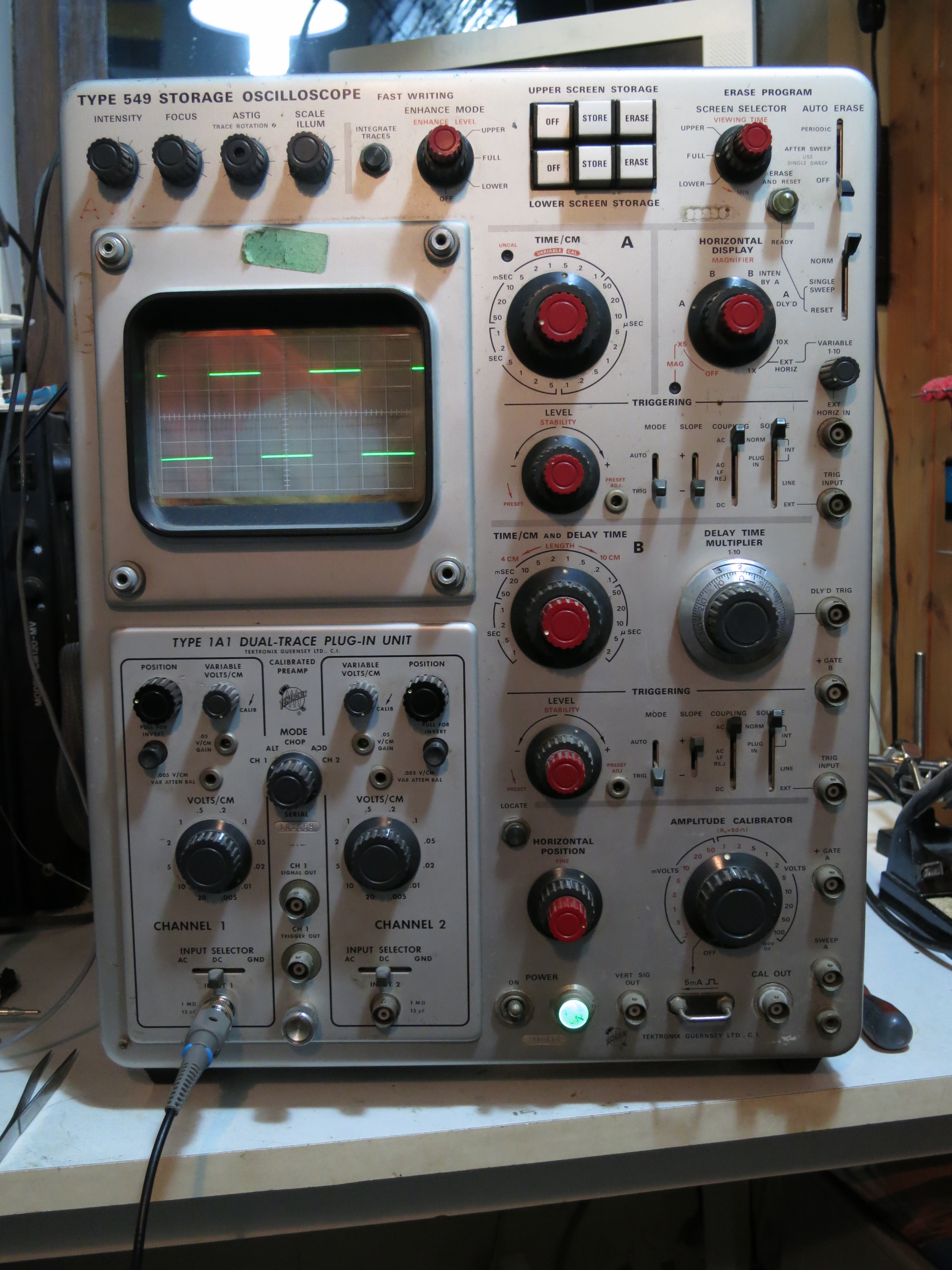
I put the transformer in the oven to soften the varnish so I could dismantle it (150 degrees C for about 15 minutes). Unwrapping the winding, removing 20 turns was easy – they were all on the first layer, so I only had to unpeel one layer of tape. I temporarily put the transformer back in the scope and tried it. Success! I could follow the instructions for setting the intensity in the manual: set to single sweep, so the trace should be blanked, turn the front panel intensity control to maximum and adjust the internal intensity range control so the spot is just visible. It was well within the range of adjustment of the control.

With the EHT working properly, I checked the voltages: the cathode is fixed at -3700V. For normal trace brightness the grid is at about -3750V, and about -3800V hides the trace entirely.

Incidentally, I was mistaken about how the intensity control works in my comments in part 2. Having studied it more carefully, the EHT supply regulates the cathode voltage to be -3700V. The intensity control varies the voltage on the ‘top end’ of the cathode winding between about +10 and +100V so the power supply has to work more or less hard to maintain -3700V at the cathode. That results in the voltage on the grid winding varying by about the same amount, so the intensity varies.

I also sorted out the horizontal sweep problem. I found a racing car in the relevant bit of the circuit diagram, but it seemed to be missing in the scope itself.

IMG_4631

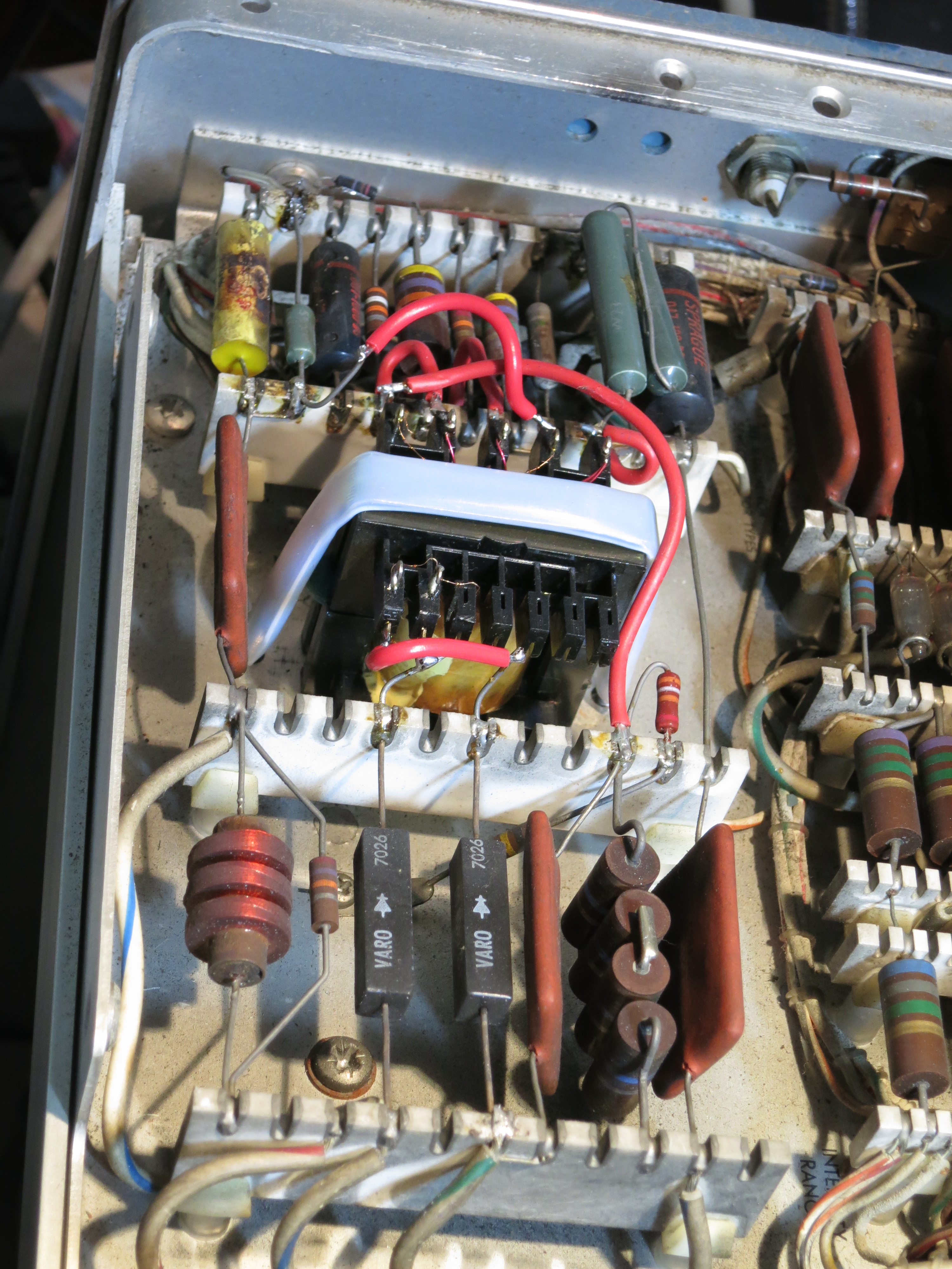
That wasn’t the problem, though. After checking the voltages around the horizontal amplifier, it became clear that R352, a 402k resistor which feeds a voltage from the normal/magnified registration preset control into the horizontal output stage, was open circuit. I replaced it and the trace looks good now, and can be adjusted properly.

IMG_4629

Now to find out why the delayed timebase doesn’t work. Oh, and I slipped with my high voltage probe whilst checking it on the 500V connection on the storage PCB, and shorted it to another pin, destroying two transistors and two diodes in the ‘enhance’ circuit. Oops.

Tektronix 549 Storage Oscilloscope, part 2

In part 1, I established that this scope was just about working but there was some problem with the high-voltage (EHT) power supply to the tube which was making the trace very dim. The transformer in the power supply is not original, so I don’t know whether it’s correct or has ever worked properly.

The design of the EHT supply in this scope is quite clever. The tube needs about 4kV between cathode and anode to make the electrons fly fast enough to light the screen up. However, there’s lots of metalwork near the anode (especially the deflection plates) which need to be at roughly the same voltage as it. It would be inconvenient, not to mention dangerous, to have most of the scope sitting at 4kV, so instead they put the anode at about 300V and the cathode and grid at -3700V. The electrons don’t know the difference, and the electronics get simpler.

However, there is still a need to change the voltage of the grid relative to the cathode, in order to control the brightness and, for example, blank out the beam on its way back across the screen. The way it’s done in the 549 is to have two separate -3700V power supplies, one for the grid and one for the cathode. Then, by controlling the voltage at the ‘top’ of each power supply separately, we can control the voltage of the grid and cathode independently. The circuit diagram here shows the arrangement.

IMG_4632

T801 is the EHT transformer. The bottom winding feeds the cathode and the top winding feeds the grid. Notice how the intensity control operates on the top end of the bottom winding: by varying the top between about zero and 100V, the bottom of the winding varies between about -3700 and -3800 V.

For this arrangement to work properly, it’s important that the two power supplies are near enough identical. If they’re not quite the same, then the grid and cathode will be too far apart in voltage, and the trace will either be very dim or uncontrollably bright. The good people of the TekScopes Yahoo! group confirmed this theory, and suggested checking whether the power supplies were the same.

A quick way of doing this without disturbing too much was to just swap the connections to the two windings on the transformer. If the transformer isn’t the cause of the problem, this should make no difference to the fault. If the transformer is the problem, the very dim trace should become bright. Switch on, with the intensity controls at minimum just in case there’s a risk of damaging the tube, and:

IMG_4625

A trace! Success. So the transformer is the culprit. Whoever rewound it has not made the two secondary windings quite the same, so I’ll have to modify it. Though there’s now a trace, it’s impossible to extinguish it using the intensity controls, and the spot is still visible during flyback, so the scope isn’t quite usable yet.

Tektronix 549 Analogue Storage Oscilloscope, part 1

IMG_4628

I’ve recently been bringing this beautiful old scope back to life. It’s one of the last models in Tektronix’s legendary 500 series of oscilloscopes, which were in production from the 1950s until the early 1970s. It has the extraordinary build quality and attention to detail of that era of Tektronix equipment, and was seriously expensive. If you had £2000 burning a hole in your pocket in the late 1960s, you could have bought an E-Type Jaguar or a scope like this one. The 549 is particularly unusual because it’s the only one of the 500 series which has a storage tube, so it’s capable of storing any signal you can capture using any letter or 1-series plugin, which makes for a very versatile instrument. It’s also full of cosy, warm, glowing valves.

This particular instrument has clearly had some repairs done in the past. There are some untidy diode and resistor replacements in the power supply, and the 4kV EHT supply has had a rewound transformer fitted and various other components replaced. I’d seen it switched on before I got it, but had never seen it produce a trace. The photo below shows the modified EHT supply, complete with new transformer.

IMG_4627

I switched it on for a quick ‘smoke test’. There was no smoke, but little else either: the power indicator and graticule illumination worked, but there was nothing to be seen on the screen even when I set the controls to settings which should show at least a spot.

The first job was to check the power supplies. These Tektronix scopes have an elaborate regulated power supply arrangement which provides -150V, +100V, +225V, +350V and +500V rails. They were all present, if a tiny bit low, but a quick adjustment of the -150V supply (to which all the others are referenced) brought them within spec. So far so good, but still no trace.

It turns out that this scope, unlike the 535A I used to use every day, has transistors in it as well as valves. Though they don’t glow nicely, they still need to get power from somewhere. In this case it’s an extra -12.4V rail I hadn’t noticed before. My meter measured zero volts, which was definitely wrong. The 12.4V regulator only has three transistors in it. Probing around the circuit showed that almost every voltage was wrong in it. The two smaller transistors were in sockets, so I experimentally wiggled them and they both fell off in my hand! Their leads had corroded right through during storage. That wasn’t going to help the power supply work. According to the circuit diagram they were NPN types and didn’t seem to be doing anything exotic, so I  got a couple of trusty BC107s, conveniently in the same TO18 package, and put them in. Switch on – and the 12.4V rail is back. Success.

Now we have a trace! The trouble is, it’s rather dim. Very dim, in fact. And somewhat skewed off to the right hand side – the horizontal position control can’t bring the left hand end of the trace much further than the centre of the screen. But timebase A works, the controls on the plugin (I’m testing using a 1A1 which I know works) do the right things, and the trace can be focused. Even better, the storage functions seem to work: I can record the trace on the screen and erase the upper and lower halves of the screen independently. That means the tube (which is irreplaceable) is almost certainly OK. Curiously the stored trace is much brighter than the ‘live’ one.

But why is the trace so dim? I looked at the setup procedure in the manual, and it turns out that the ‘intensity range’ control is already at maximum. Someone’s been here before. Maybe the repaired EHT supply isn’t working well? I rigged up a pair of AVO 8s in series as an ad-hoc 5kV meter (don’t try this at home, dear reader) and it set easily to the required 3700V. One secondary leadout wire of the replaced transformer has a habit of sparking to ground, so its insulation will need attention. But the EHT is correct, so that’s not the cause of the dimness. More investigation required – see part 2.

Dangerous Counterfeit Mains Cable

The other morning I went to plug in a piece of equipment on my work bench. It needed a standard IEC-type power cable. My workshop, like many others, has a box in the corner containing an assortment of such power cables. I can’t remember where most of them came from, and I just grabbed the first one.

It seemed rather short, only about one metre long. That didn’t matter for this job. But I noticed that the insulation was damaged near the IEC connector. Oh dear. That makes the cable unsafe to use, so I set about destroying it before throwing the parts away. My usual technique for that is to put one foot on the plug and pull hard, tearing the cable out and rendering the whole thing unusable scrap. But I got a surprise: the cable more or less came apart in my hands!

I examined it more closely and found the oddest colour code I’ve ever seen:

DSC_0466

Where on earth is the mains wiring colour code blue, black and black with a turquoise stripe? Not anywhere in Europe, that’s for sure. I looked further, taking the fuse out of the plug. Sharp-eyed readers will already have noted that the fuse is rated at 3A but coloured brown. That’s an oxymoron: under the British Standard BS1362, 3A fuses are red and 13A fuses are brown. So which was this one? It certainly doesn’t comply with the standard in spite of the ‘BS1362’ written on it.

Time to test the fuse. I hooked it up to my big power supply, and cranked up the current.

DSC_0471

Yes, you read it right. This fuse labelled ‘3A’ carried 26.6A for long enough for me to pose it for a photo, pick up the camera and press the button. It blew a few seconds later. That’s the sort of behaviour I’d expect from a 13A fuse, not a 3A one. Oh dear.

I went back to the cable, and noticed that I could easily pull apart the insulation – both the thick outer and the inner cores – with my bare hands. No tools required, not even fingernails.  That’s unbelievably dangerous. Once I’d peeled some insulation off, there was hardly any copper inside the wires:

DSC_0472

My finger-in-the-air estimate of the safe current carrying capacity of this wire would be less than 1A.

What a cable. The connectors on both ends (which I forgot to take a photo of) were covered with various approval logos. I can’t believe this thing met any safety standards. The wire itself was so weak that it could be peeled back to bare copper with just my fingers. The plug fuse was mislabelled and far too large for the rating of the cable. The cable was so thin it wouldn’t handle the load that an IEC connector is designed for without dangerously overheating. If a fault had developed in the appliance plugged in with this cable, it’s likely that the cable would simply have caught fire before the fuse blew.

I believe that this cable was supplied with a Chinese USB hard drive enclosure I bought a few weeks ago, but I can’t prove it. If you buy cheap electrical goods, check the mains cable carefully. I don’t know whether to call this one fake, counterfeit or just bad, but it was certainly a death trap.

150W Boost Converter Schematic

In a recent project, I needed a boost converter to step up 5V to about 8V at a few amps. A few different Chinese-made boost converter modules are available from various sources: I’ve seen them on eBay and Amazon. One very common one is known as the ‘150W Boost Converter’. I believe it’s intended for charging laptops from car batteries. It’s specified to take an input of 10-32V and output 12-35V, which isn’t quite what I was looking for, but the price was right so I thought I’d take a chance. This is what I found.

boost

I had a good look at the circuit board. It’s based on the UC3843 chip, which is a pretty old device (I think it dates back to 1984) and is often found in PC power supplies. However, its age and ubiquity means that documentation on it is readily available. I traced out the circuit, so here’s the schematic diagram:

150W_ boost

You can also have it as a PDF file: 150W_ boost.

It’s a pretty straightforward boost converter topology with a MOSFET switching transistor and a variable resistor in the feedback loop to set the output voltage. There is no over-current, over-voltage or reverse polarity protection at all, and the chip isn’t designed for low power consumption so this module wouldn’t be suitable where very low standby power is a requirement. There are a couple of interesting features, though.

The circuit includes an arrangement with an NPN transistor which feeds some bias to the current sense feedback loop. According to the UC3843 datasheet, this improves the stability of the converter at duty cycles higher than 50%.

The control supply for the UC3843 is derived from a 9V regulator, so it’s independent of the input or output voltage. This is convenient.

The UC3843 is designed to operate from fairly high supply voltages, and won’t start up until its supply voltage reaches 8.4V. That was a bit of a problem for my application, where the input voltage was only 5V. However, there’s nothing to say that the chip power supply has to be the same as the power input. In fact, the module already has a handy 9V regulator which feeds the control chip. Looking at the circuit diagram, there are even a pair of resistors (I’ve labelled them R1 and R2) which select whether that regulator is fed from the input or the output. As supplied, R2 was fitted, so the control chip was fed from the output. Here’s a closeup of the relevant part of the board showing R1 and R2.

DSC_0310crop

My application happened to have a low-current 12V supply available, which would be perfect for powering the UC3843. I simply removed R2 and connected my 12V supply to the point where the black arrow is in the photograph. The boost converter now worked perfectly with a 5V input.

I also had to modify it a little to be able to reduce the output voltage below about 11V. R3, labelled in the photo, is part of the feedback network. I simply removed it and replaced it with a piece of wire. Now the output voltage was variable down to 5V, and I was able to set it to the 8V I wanted.

The module seemed very comfortable delivering 3.3A at around 8V, and drew about 5A from the the 5V input. The heatsinks only got slightly warm.

Unfortunately, the power supply I wanted to run the converter and its load from didn’t like starting up with it all connected. This is quite often a problem with boost converters, since the inrush current at startup can be very large as the controller tries to bring the output up to voltage as quickly as possible. I solved this by adding a soft-start circuit to the module. More on that later.

Welcome

Here I’ll be posting technical notes from my workshop from time to time. There will probably be some open source software and hardware for you to help me debug, and almost certainly bits and pieces about old technology which has taught me things I’d like to share.