Tag Archives: embedded

Quick-and-dirty partition resize with Acronis True Image

A little embedded Linux magic comes in unexpectedly handy. Years ago, I started using Acronis True Image to back up my office PC. Other backup packages are available, as they say, but it’s worked well enough for me. This week I had reason to use it in earnest.

img_20180619_112420

The PC is set up with two main partitions on the disk. There’s one for the operating system (Windows 10) and applications, and another with data on it, analogous to the /home partition on a Linux system. Inevitably, it turned out that the boundary between these partitions was in the wrong place. The operating system partition was full, and things were starting to fail. Time to make sure the backup is up-to-date and then to restore to differently-sized partitions.

The operation fell at the first hurdle. Acronis True Image will create a ‘recovery’ USB stick from which the PC boots. This contains a small Linux distribution (Acronis Linux) and a GUI for managing the recovery operation. My backups are on a network drive, which happens to be an Apple Time Capsule. Would the Acronis recovery system connect to the Time Capsule? Would it ever. I couldn’t even persuade it to ask for the username and password, though it could see the Time Capsule on the network.

In Acronis Linux, pressing ctrl-alt-F2 in time-honoured fashion brings up a command line. Yay! Power! A bit of digging reveals a command called asamba which can connect to SMB shares. Using that, I could connect to the Time Capsule absolutely fine and mount it to the local filesystem. So why couldn’t the GUI do it? Annoying.

My next trick was to copy the backup from the Time Capsule to a USB hard drive using another Linux PC. It took a while for the several hundred gigabytes, but it got there. Acronis recovery will read USB drives, so the next step should be easy, right? No. My USB drive happened to be formatted ext4. Though Acronis Linux is perfectly capable of mounting ext4 filesystems, the recovery GUI only acknowledges the presence of FAT and NTFS discs. Aargh!

The solution was to mount the USB drive on my Linux PC, then share it using Samba. Acronis recovery found and let me log on to the Samba share, and could thus see the drive and backups.

Changing the partition sizes was the next problem. The GUI only allows you to shrink partitions or to grow them in to free space. My disk didn’t have any free space. It was all partitioned and in use. I thought that shrinking the data partition would create free space that the operating system partition could grow in to, but I was caught out by the presence of a 500MB ‘recovery’ partition which Windows had sneaked in between the two. I don’t know what it’s for but I didn’t feel like taking the risk of destroying it. There are no tools in the Acronis GUI for deleting partitions and starting again, so I was stuck.

img_20180619_113338

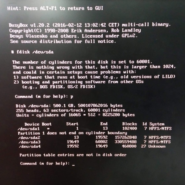
Command line to the rescue! Ctrl-alt-F2 again, and there’s a perfectly good copy of fdisk available. It was a moment’s work to delete the existing recovery and data partitions, then ctrl-alt-F1 to the GUI. Restart the restore process and there’s free space available for the operating system partition to grow in to, and plenty of room to create new recovery and data partitions.
img_20180619_112939

The restore took a few hours, as expected, but was successful. The only wrinkle was that Acronis recovery had marked the recovery partition as active rather than the boot partition, so the PC complained that there was no operating system. Another trip in to fdisk to mark the boot partition active sorted that out, and now I’m typing this very text on the PC restored to working order.

Footnote: there is another Acronis restore tool intended for restoring backups to dissimilar hardware. This may have handled the partition resizing more elegantly, but I didn’t try it.

Reliable I2C with a Raspberry Pi and Arduino

There are many ways of connecting sensors and devices to a Raspberry Pi. One of the most popular is the I2C bus. It’s great for devices which don’t need to transfer too much data, like simple sensors and motor controllers, and it’s handy because lots of devices (up to 127, or even more) can be connected to the same pair of wires, which makes life really simple for the experimenter. I’ve mentioned using the I2C bus in another blog post, because sometimes a bit of software fiddling is needed to get it to work.

Recently I’ve been working on a project involving various devices connected to a Raspberry Pi. Some of them use I2C. The project is based around a breakout board I designed for the Multidisciplinary Design Project at Cambridge University Department of Engineering, in which students collaborate in teams to put together a robot. The breakout board is shown next to the Raspberry Pi in the photo below.

IMG_1381

It fits on top of the Pi, and has lots of useful features including a student-proof power supply, real time clock, accelerometer, space for a Zigbee module, analogue inputs, diagnostic LEDs and four motor driving outputs, all wired to convenient connectors.

The analogue inputs and motor outputs are implemented by a PIC microcontroller connected to the I2C bus. The software for the PIC was written by an undergraduate several years ago. It works well, but seems to have some odd habits. I found that it would apparently work, but sometimes an attempt to read data from the PIC would just fail, or return wrong data, and sometimes data would get written to the wrong register. At first I suspected a wiring problem, but examining the SDA and SCL signals with a scope showed nothing wrong. I tested another device on the same bus – a Philips PCF8575 I/O expander – and it worked perfectly every time. That narrowed the problem down to the PIC. Since there was nothing I could do about the PIC’s software, I had to find a workaround.

I spent some time experimenting with where the communications seemed to go wrong. Reading from an I2C device usually involves two separate operations on the bus. The first one tells the I2C device which register address we want to read, and the second does the actual read. The diagram below shows the sequence. The ‘control byte’ in each case sends the address of the I2C device (0x30 in this case) plus a bit indicating read or write.

smbus-transaction

I found a pattern in the failures. From time to time, the write operation which sets the register address would fail, reporting ‘I/O error’. After that, reading the data would return the wrong value. I modified my code so that if the write operation failed, it would retry a couple of times before giving up. It turned out that retrying was always successful, if not on the first attempt then on the second. However, the data read would still return the wrong value. The value returned was always the address of the register I wanted! It seemed as if something was getting stuck somewhere in the I2C system. Whether it was in the Linux drivers, or the PIC software, I don’t know, and I didn’t spend long enough to find out. My assumption is that the PIC software is sometimes just too busy to respond to the I2C operations correctly.

I tried the retry strategy again, and it turned out that the second attempt to read the data byte always got the right value. The algorithm to read reliably looks like this, in pseudo-code:

  if (write_register_address() fails)
    retry up to 3 times;

  read_data();
  if (we had to retry writing register address)
    read_data();

In practice I was using the Linux I2C dev interface to implement this. Yes, it’s a bit of a nasty hacky workaround, but it did get the communications working reliably.

There was another device I wanted to talk to: an Arduino Mini running a very simple sketch to return some sensor data. This also used the I2C bus. There are handy tutorials about how to get an Arduino to behave as an I2C slave device, like this one. The I2C interface is implemented nicely by the Wire library. Implementing a slave involves responding to two events: onReceive and onRequest.

The onReceive event is called when data, like the register address, is written to the slave, and the onRequest event is called when the master wants to read data. My initial code looked like this:

Wire.begin(I2C_ADDRESS)
Wire.onReceive(receiveEvent)
Wire.onRequest(requestEvent)

void receiveEvent(int bytes) {
  registerNumber = Wire.read();
}
void requestEvent() {
  Wire.write(registers[registerNumber];
}

This worked most of the time, but after a few thousand transactions, it would appear to ‘lock up’ and ignore any attempt to change registers – it would always return the same register, and in fact no more onReceive events were ever generated. Of course, it turned out to be my fault. When reading data in the onReceive event code, it turns out to be important to make sure that data is actually available, like this:

void receiveEvent(int bytes) {
  while(Wire.available())
    registerNumber = Wire.read();
}

That solved the problem. It’s annoying that reading non-existent data can lock up the whole I2C interface, so watch out for this one if you’re using an Arduino as an I2C slave.

Systemd for Embedded Linux

Over the last few years, there has been a lot of controversy in the Linux world about systemd. As I understand it, systemd is intended to be a better-engineered, more powerful version of the motley collection of little programs and scripts which keeps the essential services on a Linux system running.

systemctl

The controversy arises because the original 1970s Unix way of doing things was to rely on a motley collection of little programs and scripts for everything, each of which was simple but well understood, and to knit them together to form a complete operating system. Systemd takes a different approach, using larger and more sophisticated components which are more dedicated to particular tasks, such as managing services or network connections. This is supposed to make it more efficient and easier to manage in the twenty-first century.

I’ve been doing some work recently on an embedded Linux system which runs on the latest version of Debian Linux, version 8 (‘Jessie’). Debian Jessie fully supports systemd to the extent that it seems to be the default way of doing things. I thought I’d experiment with it a bit.

When working on an embedded Linux system, I very frequently want to have a piece of my software run reliably at startup, get restarted if it fails, and be able to output logging information to an easily-managed place. In this case, my software provides a D-Bus interface to a piece of industrial electronics.

In the past I’ve relied on copying and pasting scripts from other pieces of software, and managing log files has always been a bit of a mess. It’s hard to do these things right, so re-inventing the wheel is too risky, which means that the best strategy is to copy somebody else’s scripts. I have never counted the hours of my time which have been wasted by dealing with awkward corner cases and peculiar bugs due to recycled scripts behaving in ways I hadn’t anticipated.

What does it look like with systemd? There are some helpful tutorials out there, including this one from Alexander Patrakov, so it didn’t take me too long to put together a service file which looks like this:

[Unit]
Description=My D-Bus Gateway
[Service]
Type=dbus
BusName=com.martin-jones.gateway
ExecStart=/usr/bin/my_dbus_gateway
Restart=always
[Install]
WantedBy=multi-user.target

I’ve changed the names to protect the innocent, but the contents of the file are pretty self-explanatory. The [Unit] section just includes a description which is readable to a human being. The [Service] section describes the service itself. In this case it’s of type  dbus, which means that systemd will check that the service name (com.martin-jones.gateway in this case) gets correctly published on to D-Bus. The Restart=always setting means that my software gets restarted if it exits. The [Install] section just indicates that this service should run when the system comes up in multi-user mode (like the old runlevel 5).

Having created this file, I simply copied it into /etc/systemd/system/my_dbus_gateway.service and, lo and behold, my new service worked. It was immediately possible to manage the service using commands like

systemctl start my_dbus_gateway.service
systemctl stop my_dbus_gateway.service
systemctl status my_dbus_gateway.service

Great! That’s exactly what I wanted.

Now for logging. I’d heard that systemd would log the stdout and stderr outputs of services into its own journal, and forward that to syslog as required. It does, but there’s a subtlety. Output from stderr appears in /var/log/syslog immediately line-by-line, but output from stdout gets aggressively buffered. This means that it gives the appearance of not working at all unless you explicitly flush the stdout buffer in your code using something like

fflush(stdout)

That’s the only wrinkle I came across, though.

In summary, using systemd’s facilities has made my life as an embedded Linux developer much, much easier and hopefully more reliable. That’s a good thing. My top tips for getting your software working under systemd are these:

  • Create your .service file using the recipe above and the documentation
  • Don’t forget to flush stdout if you want to see it in syslog.

Lattice FPGA programming adapter from the junk box

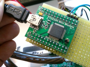
Working with Lattice FPGAs recently, I had a need to program one but couldn’t find my ‘proper’ (Chinese clone, bought from eBay) programming adapter. When I started the Diamond Programmer software, though, it claimed it could see a USB programming adapter. It turned out that I’d left an FTDI ‘FT2232H Mini Module‘ attached to the PC. I use the module for all sorts of little debugging exercises: most often as a dual serial port for serial port debugging, but it also works for programming Parallax Propeller microcontrollers.

Img_0603

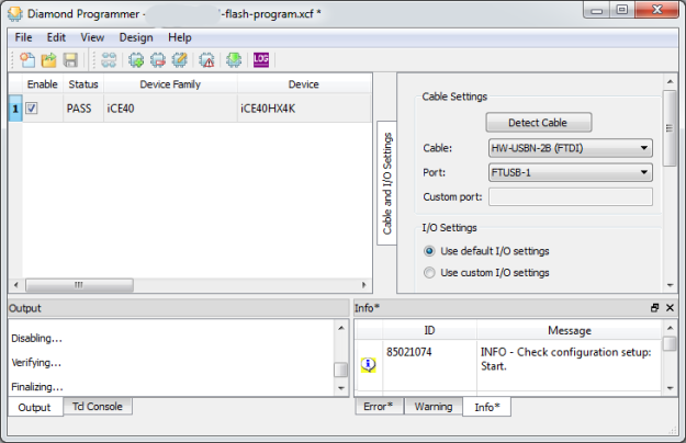
As luck would have it, the Diamond software recognises the unadulterated FT2232H as a legitimate USB programmer, and pressing the ‘Detect Cable’ button finds it. Note that if you plug in a new USB device, the Diamond Programmer software needs restarting before it can see it.

The FT2232H has two ports, A and B, and these appear as ports FTUSB-0 and FTUSB-1 in the Diamond software. All that remained was to figure out the wiring. Fortunately, there are a lot of clues in the schematics of various Lattice evaluation boards, particularly the MachXO2 Pico Board and the iCE40 Ultra Breakout Board.

diamond-programmer

Here’s the wiring, both for SPI and JTAG, referred to the pins on the Mini Module. I chose to use port B since it was more convenient for my prototype board. Translating the wiring to port A is left as an exercise for the reader.

SPI    JTAG  FT2232H  Mini Module
SO     TDI   DBUS1    CN3-25
SI     TDO   DBUS2    CN3-24
SCK    TCK   DBUS0    CN3-26
SS_B   ISPEN DBUS4    CN3-21
CRESET TRST  DBUS7    CN3-18
GND    GND   GND      CN3-2,4

It works well, and does exactly what it should.

Dealing with Shellshock on Debian Squeeze for ARM

Today’s announcement of the Shellshock Bash vulnerability had me worried. I run lots of Debian Linux systems, and they’re not all the latest version. Many are still Debian Squeeze (version 6) which no longer gets security updates as standard. That’s my fault, of course, and I should have upgraded, but I haven’t. Yet. Now I’m more motivated to do it. However, upgrading to Debian Wheezy (version 7) isn’t something I wanted to do in a hurry, especially on remote machines.

Debian have thought of people like me, and there is a ‘Long Term Support‘ option for Debian Squeeze, which is great, and includes the necessary security update to Bash. The trouble is, it only supports i386 and amd64 processors, and the machines I’m worried about are ARM (specifically armel) ones.

I was left with one option: build the new Bash from source. Fortunately, Debian Squeeze LTS has the source available, so I was able to do this. Here’s how. This might be useful to other Debian ARM users who are none too fastidious about keeping up to date.

I added the line

deb-src http://http.debian.net/debian squeeze-lts main contrib non-free

to /etc/apt/sources.list, and did

apt-get update
apt-get source bash

which fetched the source code. Then I had to build it.

cd bash-4.1
dpkg-buildpackage -b -us -uc

This complained bitterly about a load of missing dependencies, which I dealt with:

sudo apt-get install autoconf autotools-dev bison libncurses5-dev debhelper texi2html gettext sharutils texlive-latex-base ghostscript

which was a royal pain due to lack of disc space. Beware, these packages want about 180MB of disc space (plus about 80MB for the package downloads) so might need some care on a small system. I started by installing packages individually, doing ‘apt-get clean’ after each one, but texlive-latex-base is an absolute monster and I had to do some filesystem reshuffling to get it to install. I hope you don’t have to.

During the build (repeating the dpkg-buildpackage command above) the patch for ‘CVE-2014-6271‘ was mentioned, which was reassuring. The actual build process took a while – about half an hour on a 1GHz-ish ARM chip (a SheevaPlug).

The build completed successfully, so I was able to install the new package:

cd ..
sudo dpkg -i bash_4.1-3+deb6u1_armel.deb

and then start a new shell and try the test:

env X="() { :;} ; echo busted" `which bash` -c "echo completed"

on a ‘broken’ version of Bash, this will print

busted
completed

but on a fixed one, it prints

/bin/bash: warning: X: ignoring function definition attempt
/bin/bash: error importing function definition for `X'
completed

which is the right answer, and means that the vulnerability is patched. It worked!

I hear that the fix isn’t complete, though, so more work may be required later.

SD memory card access from an Atmel AVR microcontroller using sd-reader

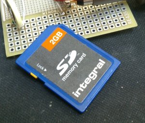
I’ve recently had a need to access SD memory cards from an Atmel AVR microcontroller. There are plenty of libraries out there which can do it, which saved me a lot of time, but choosing the right one and getting it to work wasn’t entirely straightforward.

DSC_1025

I looked at sdfatlib, which is intended for use with the Arduino. The Arduino also uses an AVR microcontroller but the code is mostly written in C++. My project (using Atmel Studio) was set up to build a lot of complex code in C, and I didn’t fancy trying to convince it to build C++ and link successfully. The compiler balked at the first mention of the word ‘class’, so I decided not to pursue it.

Next in the candidate list there was FatFs, which is written in C but targeted at all sorts of microcontrollers including the AVR. It looked more generic than I needed, and I didn’t want to spend too much time dealing with the low-level SPI stuff to talk to an SD card, so I moved on. I would certainly consider it for future projects though.

The final choice was sd-reader, written and released by Roland Riegel. This was the answer to my wishes: all written in C and well tested, specifically targeted at SD cards on AVR microcontrollers. It compiled as part of my project without a problem. However, there were some issues to deal with.

Firstly, it’s set up assuming that it has sole control of the SPI interface. My project already used SPI for another peripheral, so I had to do some trickery in sd_raw_config.h and my existing code to dynamically reconfigure the SPI port for each peripheral each time it was selected. I replaced the macro:

#define select_card() PORTB &= ~(1 << PORTB0)

with

#define select_card() ({SPCR=0x50; nSD_CS_PORT &= ~nSD_CS_MASK;})

which forced SPCR, the SPI control register, to the right value for the SD card. I had to do something similar in my other peripheral code. This all worked fine but a small change to sd_raw_init() in sd_raw.c was needed because the initialisation of the card takes place with a very slow clock speed, so that accesses SPCR as well.

I wanted to enable access time stamping in my application, so I set

#define FAT_DATETIME_SUPPORT 1

in fat_config.h. The documentation indicates that functions fat_set_file_modification_date() and fat_set_file_documentation_time() are available, but in fact they’re not. They’re declared static and used internally by the sd-reader code. The way to get time stamps to work is to define a function:

void get_datetime(uint16_t* year, uint8_t* month, uint8_t* day, uint8_t* hour, uint8_t* min, uint8_t* sec)

which gets called by the sd-reader code. You write this function so that your timekeeping code fills in the values. It worked fine once I’d discovered this.

The final wrinkle was that the function to create a directory:

uint8_t fat_create_dir(struct fat_dir_struct* parent, const char* dir, struct fat_dir_entry_struct* dir_entry)

is claimed by the documentation to leave dir_entry filled in with the directory’s details if the directory already exists. It does, but returns 0 indicating an error, so there’s no way to tell if it was impossible to get the directory or it just already existed. I worked round this by attempting to open the directory first, and only if that failed, attempting to create it.

Caveats: I may not have been using the most up-to-date version of the software, or I may have misinterpreted the documentation, or these things might have changed since I wrote this text.

Installing balloonboard.org Debian Linux build on a Raspberry Pi

I’ve just successfully got Debian Linux running on a Raspberry Pi, having built it entirely from the balloonboard.org distribution. Why might you want to do this? Well, I did it because it gives me a small, clean Debian Linux installation which I can then customise. Here’s how I did it.

Get the software:

svn checkout svn://balloonboard.org/balloon/branches/menuconfig2
make menuconfig
  • Mode Expert mode
  • Balloon Board Raspberry Pi board
  • Choose which buildroot version to build -> Feb 2013
  • Select kernel version 3.8 (rpi)
  • Select Build boot image
  • Select Build kernel modules
  • Select Build initrd kernel
  • Select Build Raspberry Pi boot patition image
  • Select Build Debian Root Filesystem

Now type make and it should all build.

Create yourself an SD card with two partitions on it: one smallish FAT partition for the boot files, and a big ext4 one for the root filesystem. Don’t forget to format them.

Into the FAT partition copy the contents of build/kernel/rpi-initrd-boot. Into the ext4 partition untar the file build/rootfs/debianrootstrap.modules.tgz.

Now put the SD card into your Pi and switch it on. This should boot into a ‘recovery kernel’ which has a minimal root filesystem in its initial ramdisk, just enough to sort out the ‘proper’ root filesystem. I used the console serial port to work with it. The HDMI and USB ports might also work but I haven’t tried them. It should come up with a login prompt. Log in as root, password rootme.

Now to configure the root filesystem:

mount /dev/mmcblk0p2 /mnt/root
chroot /mnt/root

Finish the Debian installation (this has to be done now because some aspects of it need to run on the ARM processor, so it’s not easy to have your PC do it). It will ask you questions about time zones and things:

/var/lib/dpkg/info/dash.preinst install
dpkg --configure -a

Set a password for the root account so you can log in

passwd root

and add the serial port to the list of secure ports which are considered safe for root logins:

echo /dev/ttyAMA0 >> /etc/securetty

And shut things down

halt

That last step will probably produce an error message, but it doesn’t matter as long as it’s written everything to the SD card.

Now put the SD card back in your PC, and copy the contents of build/kernel/rpi-boot into the FAT partition. That contains the real kernel which will mount the newly-minted root filesystem. Put it back into the Pi and boot. It will ask you to change the root password at first login.

It worked for me, though I had to ‘ifdown eth0’ and ‘ifup eth0’ again to get Ethernet to work. From that point on I was able to install Debian packages normally.

How to get the second Raspberry Pi I2C bus to work

One of the useful interfaces on the Raspberry Pi is the I2C bus. Originally invented by Philips in the 1970s for controlling functions inside consumer electronics, especially TVs, it’s still very handy for connecting up lowish-speed peripherals to computers. Some of the most popular are real time clocks like the MCP7940, amongst many others, and general purpose input-output chips like the venerable PCF8574. One of its convenient features is that it only involves two wires: SCL (clock) and SDA (data).

pi2c

The Raspberry Pi originally exposed one I2C bus on its GPIO connector, P1. It had another I2C bus dedicated to the camera connector, S5. However, with revision 2 of the Raspberry Pi, another connector was added. This was P5, squeezed in next to P1, and it also carried the second I2C bus, making it easier to get at and use. However, for some reason the two I2C buses got swapped over between revision 1 and revision 2. And to add a further layer of complication, the camera connector and P5 are wired to different GPIO pins on the processor, even though they are both logically the same bus. I’ve tried to summarise the situation in the table below.

Revision 1 Revision 2
GPIO0 SDA0 P1 pin 3 SDA0 S5 pin 13
GPIO1 SCL0 P1 pin 5 SCL0 S5 pin 14
GPIO2 SDA1 S5 pin 13 SDA1 P5 pin 3
GPIO3 SCL1 S5 pin 14 SCL1 P5 pin 4
GPIO28 SDA0 P1 pin 3
GPIO29 SCL0 P1 pin 5

Working on the CUED MDP project recently, I had a need to get the both I2C buses working on a revision 2 Raspberry Pi. There was no problem with the one on P5: typing

i2cdetect -y 1

showed the devices I had connected to it. But

i2cdetect -y 0

showed nothing at all, and examining pins 3 and 5 of P1 showed no activity. Disappointing. After a bit of digging, it seemed to me that the standard Raspberry Pi Linux kernel configures the processor to use GPIO 0 and 1 as I2C bus 0, and GPIO 2 and 3 as I2C bus 1. I wanted the bus on P1 to work, so I needed GPIO 28 and 29 to be my bus 0.

The BCM2835 processor on the Raspberry Pi, like most modern integrated processors, can have its pins programmed to do various different functions. In this case I needed to disable I2C on GPIO 0 and 1 and enable it on GPIO 28 and 29. To do this I enlisted the help of Mike McCauley’s BCM2835 library. It makes reprogramming the GPIOs fairly straightforward.

To install the library on your Raspberry Pi, make sure it’s connected to the internet, then:

wget http://www.airspayce.com/mikem/bcm2835/bcm2835-1.26.tar.gz
tar xzvf bcm2835-1.26.tar.gz
cd bcm2835-1.26
./configure
make
sudo make check
sudo make install

By the time you read this, there might be a new version of the library, so check on Mike’s site to see what you’re getting.

The C code to set up the bus looks like this:

#include <bcm2835.h> 

#define BCM2835_GPIO_FSEL_INPT 0 
#define BCM2835_GPIO_FSEL_ALT0 4 

main() {
    bcm2835_init(); 
    bcm2835_gpio_fsel(0, BCM2835_GPIO_FSEL_INPT); 
    bcm2835_gpio_fsel(1, BCM2835_GPIO_FSEL_INPT); 
    bcm2835_gpio_fsel(28, BCM2835_GPIO_FSEL_INPT); 
    bcm2835_gpio_fsel(29, BCM2835_GPIO_FSEL_INPT); 

    bcm2835_gpio_fsel(28, BCM2835_GPIO_FSEL_ALT0); 
    bcm2835_gpio_set_pud(28, BCM2835_GPIO_PUD_UP); 
    bcm2835_gpio_fsel(29, BCM2835_GPIO_FSEL_ALT0); 
    bcm2835_gpio_set_pud(29, BCM2835_GPIO_PUD_UP); 
}

It initialises the library, sets GPIO 0 and 1 as normal inputs (thus disabling their I2C function) and enables GPIO 28 and 29 as alternate function 0 (I2C bus), with pullup enabled. To build it, cut and paste the code into a file. I called it i2c0.c. Then compile it:

cc i2c0.c -o i2c0 -lbcm2835

and run it:

sudo ./i2c0

Now I2C bus 0 will be active on P1. Well, it worked for me. Once the code is compiled, of course, you can just run ‘i2c0’ after booting the Pi.

I realise that in future this will probably be made obsolete by changing the device tree sent to the Linux kernel at boot time, but for now it’s useful!

Cross-building for ARM on Debian squeeze and lenny

I have to support some software running under Debian Linux 5.0 (lenny) on ARM hardware. The operating system on this hardware can’t easily be upgraded because it’s expensive to get at physically, but there is a mechanism for updating the application it runs. This is an interesting problem in maintaining old software. The ‘stable’ releases of Debian have a reputation for being rather infrequent and almost out-of-date by the time they’re released, but in this case, a release every two years is too often! In embedded applications, having the latest and greatest doesn’t matter as long as it works and doesn’t change.

I have recently had to build a new release of the application software for this ARM hardware. My main Linux machine is now running Debian 7.0 (wheezy), which does a great job of cross-building for ARM, but unfortunately the resulting binaries are linked with libstdc++.so.6.0.17. The old lenny machines have version 6.0.10, which is too old to run these binaries.

For those not familiar with Debian Linux, the relevant versions go like this:

5.0 lenny (released February 2009)
6.0 squeeze (released February 2011)
7.0 wheezy (current as of July 2013)

I fiddled around for a while trying to install older libstdc++ packages under wheezy, but found myself in dependency hell, so I decided simply to revive an ancient PC which was already running Debian 6.0 (squeeze) and press it into service for doing the build.

Getting the ARM toolchain installed wasn’t hard. I had to add the line

deb http://ftp.uk.debian.org/emdebian/toolchains squeeze main

to /etc/apt/sources.list, and do

apt-get install g++-4.4-arm-linux-gnueabi

and it all worked. However, the code I was working on depended on a library, which I needed to install in its ARM version. There’s a handy tool, xapt, which will arrange this for you. However, it’s not natively available on squeeze but has been backported from wheezy, so I had to add

deb http://ftp.uk.debian.org/debian-backports squeeze-backports main

to /etc/apt/sources.list. Then

apt-get install -t squeeze-backports xapt
xapt -a armel libxxx-dev

and my library package was built and installed automagically. Nice.

However, this wasn’t enough. It turned out that I really had to build everything on lenny in order to get it to work – it seems that the libstdc++ from wheezy is compatible with squeeze, but neither wheezy nor squeeze is compatible with lenny.

First, I had to set up a lenny machine. This isn’t as easy as it used to be because lenny is no longer supported by Debian, and exists only as an archive. We should be grateful that it’s there at all. I set up a new virtual machine using VirtualBox and downloaded the last lenny netinst CD image (5.0.10) from archive.debian.org. There’s a problem during installation: it asks which Debian package repository it should use, but all of the available choices fail because the lenny packages aren’t there any more. The solution is to select ‘Back’ and allow it to continue without a repository. It complains, but it works. After it had rebooted, I manually edited /etc/apt/sources.list, commenting out the cdrom line and adding a pointer to the archive:

deb http://archive.debian.org/debian-archive/debian/ lenny main

Then I could install the packages I wanted (subversion, scons and other tools). Now to get the cross-building tools. Sorting out the ARM version of gcc wasn’t too hard. I added

deb http://www.emdebian.org/debian lenny main

to sources.list and was able to install gcc-4.3-arm-linux-gnueabi and g++. Apt complains about a lack of signatures, but that doesn’t stop anything working. I still had to get libssl-dev, though. The xapt tool doesn’t exist on Lenny so I had to use apt-cross, a tool which is an earlier attempt at doing the same thing:

apt-get install apt-cross

and add a source entry to /etc/apt/sources.list:

deb-src http://archive.debian.org/debian-archive/debian/ lenny main

then do

apt-cross -a armel -S lenny -u
apt-cross -a armel -S lenny -i libxxx-dev

and everything happened as it should. Now at last I could build my code and, with fingers crossed, run it on my embedded Debian Lenny machine.

I have to say that I think Debian’s support for cross-building is outstandingly good. Tools like apt-cross and xapt make it much easier than it could be, and the work continues with the multiarch project which improves support still further.

Embedded serial port debugging on the cheap

I do a lot of electronics design and debugging. It’s how I make my living. Most of the things I work on involve embedded computers of one sort or another talking to various peripherals. It could be an 8-bit microcontroller sending data to a simple data logger, or a sophisticated 32-bit Linux system communicating with a wireless modem. Many of these connections involve asynchronous serial ports. If something goes wrong, as it usually does, It’s really useful to be able to see what’s going on with the communications. Here’s a picture of the sort of thing I’m dealing with. It’s a board I designed which contains a load of power electronics as well as a microcontroller and a USB data logger which talk to each other using a serial connection. Note the 175A fuse next to the USB connector!

DSC_0511

Monitoring a serial port on a PC is relatively easy, but the ones I deal with are separate from the PC, stuck on some circuit board on the workbench or buried inside a piece of equipment. To complicate matters, I need to monitor both directions of traffic at the same time, and have some idea of what order things happened in. There are many protocol analyser tools out there which will do all sorts of clever things, but it’s hard to justify them for small projects.

Faced with a such problem to solve recently, I put together a cheap and simple system which allows a developer to monitor both directions of an embedded serial port simultaneously, and have a record of which end transmitted what, when. It consists of a software tool and a bit of hardware.

Software

The software is a simple tool I wrote in C. It compiles and runs under Linux. Given the names of two devices, it opens both of them. It waits for a character on either of them and displays it on the screen in hexadecimal and ASCII. Each device has a separate column. Every time data arrives from the other device, it starts a new line. Each line is timestamped. In this way, it produces a dump of the conversation between the two devices, and it’s clear what order things happened in, and who said what.

It has one other handy feature: it has a ‘-l’ for (‘live’) command line option. In this mode, it will update the display every time a character arrives so you can see occasional data as it happens. This is great for monitoring things like keystrokes. This mode involves a whole load of backspacing and overprinting on the display, so it’s not really suitable if you want to record the output of the tool for later examination. The non-live mode is better for that – it outputs data only when it has a complete line.

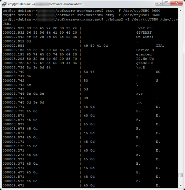
Here’s an example session using the software.

hdump2Here you can see that I used stty to set the baud rate of two serial devices attached to the PC. Then I ran the tool (provisionally called hdump2). You can see the data after that. The timestamps are on the left, followed by hexadecimal representations of the data, then the ASCII version. In this case we’re watching the initialisation of a Vinculum USB host controller. The data isn’t guaranteed to be in exactly the right order character-for-character, since it’s had to travel from two serial ports through the operating system, but it’s good enough for debugging.

The source is available to download here:

hdump2-1.0-source.tar.gz

To build it:

tar xzf hdump2-1.0-source.tar.gz
make

It’s free software, licensed under the GNU General Public License.

Hardware

The hardware can be any pair of serial ports suitable to connect to the device under test, but I made a little module which makes it easier. It’s based on an FTDI FT2232H Mini Module. In fact, that’s all it is! There are just a couple of wire links to configure its power supplies and bring the receive pin of each of its two serial ports out to a connector. There’s a load of spare space on my board which I intend to use eventually to fit various useful connectors and buffers to hook up to the different serial port standards I come across.

DSC_0516

The wiring looks like this:

  • Join pin CN3-1 to CN3-3
  • Join pin CN2-1 to CN2-11 and CN3-12
  • serial input 1 is on CN2-10
  • serial input 2 is on CN3-25
  • input ground is on CN3-2 and CN3-4

When plugged in to a PC, two devices (typically /dev/ttyUSB0 and /dev/ttyUSB1, assuming you don’t have any other USB serial ports attached) appear. They can be used as the device arguments to the tool.

Do let me know if any of this is useful to you, or if you have comments or improvements to suggest or contribute.