In a previous article, I took apart a Herrmans H-Track dynamo rear light. I wasn’t happy with how the standlight behaved: it stayed on for a very long time. Even after an hour, some glow was still visible. This is more irritating than helpful because it attracts attention to the bike when it’s parked, and many times has caused people to helpfully call, “You’ve left your light on” to me when I’ve locked up my bike.
I also saw recently a poster at a railway station telling cyclists, in no uncertain terms, to switch off their lights when wheeling their bikes on station platforms – apparently there’s a real risk of causing trouble. Train drivers are highly attuned to spotting red lights, and so having extra ones on wayward bicycles is a safety problem.
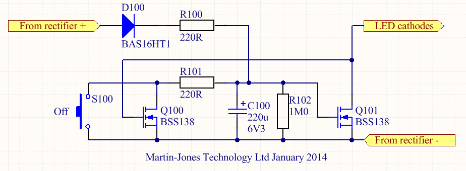
For these reasons I wanted to get some sort of control over the standlight. The German StVZO regulations (section 67, Technische Anforderung 4) say that the standlight should stay on for at least 4 minutes, so I made that my target. Most such problems these days seem to get solved with an Arduino, but that’s really boring. I wanted to do it the old-fashioned analogue way. After a bit of playing around, I came up with a little circuit which automatically switches off the standlight after 4-6 minutes, and also has a button to switch it off manually. It only uses seven components. Here’s the schematic diagram.

It’s a simple monostable multivibrator made of two transistors. When the dynamo is generating power, capacitor C100 charges up via resistor R100 and diode D100. It only charges to about 5V because there’s a 5V-ish zener diode in the main light. The voltage on C100, and thus Q101’s gate, keeps Q101 switched on so the LEDs light up. Because Q101 is conducting, there’s very little voltage on its drain, so Q100 is switched off. Meanwhile, in the original electronics of the light, the standlight capacitor is charging up so that the LEDs still get a power supply when the dynamo stops.
When the dynamo does stop generating, C100 no longer receives any charge but instead starts discharging through R102. Because C100 and R102 are both large, and Q101’s gate has a very high resistance, this takes several minutes. But eventually the voltage on C100 drops low enough (about 1.5V) so that Q101 starts to turn off. As it does so, the voltage on Q101’s drain starts to increase, which gradually switches Q100 on. Once Q100 starts conducting, C100 also discharges through R101, so the whole process accelerates. Q100 and Q101 thus form a sort of Schmitt trigger, which switches off Q101, and therefore the LEDs, fairly quickly at the end of a timing period of a few minutes.
The button S100 is there so that it’s possible to manually discharge C100 and switch the light off, for example when parking the bike. Note that this doesn’t discharge the standlight capacitor so, next time the bike starts moving, the standlight will already be at least partially charged. This is handy.
None of the components are critical. D100 can be any small-signal silicon diode, and Q100/Q101 are just logic-level N-channel MOSFETs.
I built the circuit on a little piece of matrix board. It fitted easily into spare space in the light.
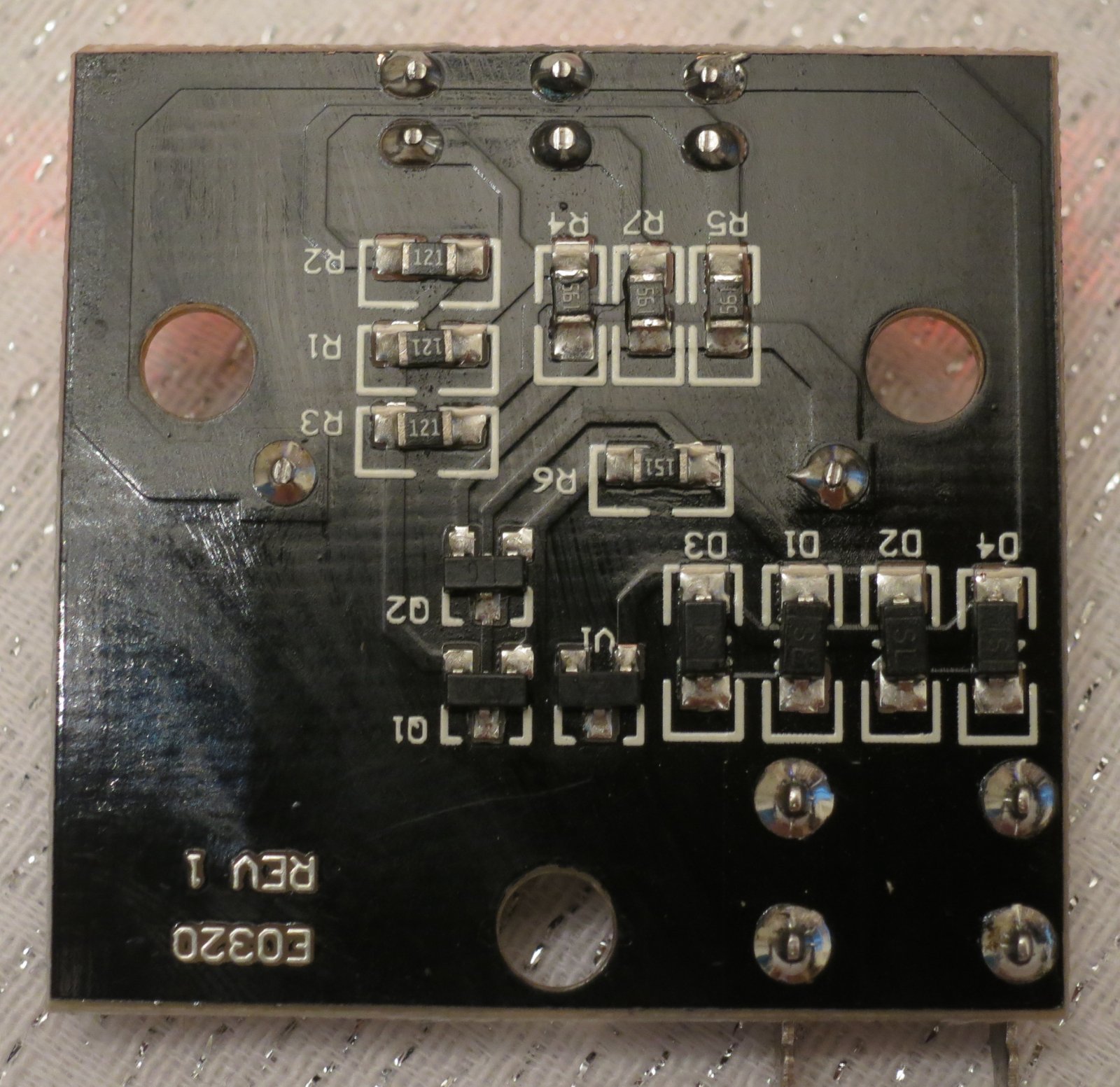
Here are the connections to the original light PCB. The green wire goes to the LED cathodes. You can make out where I’ve rather untidily cut the original PCB track to the LED cathodes. I had to cut it in two places because it was used as a ‘through route’ from the rectifiers to the rest of the electronics. The resulting gap is bridged by the bit of white mod wire soldered to D3.
 Fitting in the button, S100, was a bit more tricky. I ended up using a miniature PCB-mounting button and gluing it in into the back of the case using epoxy resin. The button protrudes through a little hole but is doesn’t stick out. I’m hoping that will protect it from damage but still make it easy to use.

The brown button is visible at the top left of this photo. When the light is mounted on the bike, it’s still accessible. I’ve been using the modified light for a few days now and I’m pleased with it. The light itself is very bright, so being able to switch it off when I stop to buy bread is properly handy.