Tag Archives: atmel

Reliable I2C with a Raspberry Pi and Arduino

There are many ways of connecting sensors and devices to a Raspberry Pi. One of the most popular is the I2C bus. It’s great for devices which don’t need to transfer too much data, like simple sensors and motor controllers, and it’s handy because lots of devices (up to 127, or even more) can be connected to the same pair of wires, which makes life really simple for the experimenter. I’ve mentioned using the I2C bus in another blog post, because sometimes a bit of software fiddling is needed to get it to work.

Recently I’ve been working on a project involving various devices connected to a Raspberry Pi. Some of them use I2C. The project is based around a breakout board I designed for the Multidisciplinary Design Project at Cambridge University Department of Engineering, in which students collaborate in teams to put together a robot. The breakout board is shown next to the Raspberry Pi in the photo below.

IMG_1381

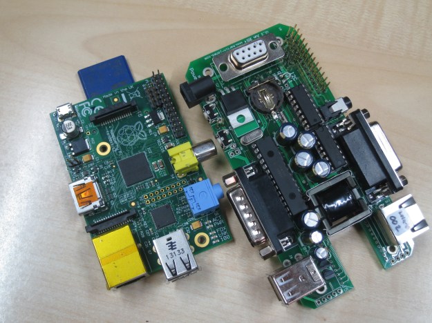
It fits on top of the Pi, and has lots of useful features including a student-proof power supply, real time clock, accelerometer, space for a Zigbee module, analogue inputs, diagnostic LEDs and four motor driving outputs, all wired to convenient connectors.

The analogue inputs and motor outputs are implemented by a PIC microcontroller connected to the I2C bus. The software for the PIC was written by an undergraduate several years ago. It works well, but seems to have some odd habits. I found that it would apparently work, but sometimes an attempt to read data from the PIC would just fail, or return wrong data, and sometimes data would get written to the wrong register. At first I suspected a wiring problem, but examining the SDA and SCL signals with a scope showed nothing wrong. I tested another device on the same bus – a Philips PCF8575 I/O expander – and it worked perfectly every time. That narrowed the problem down to the PIC. Since there was nothing I could do about the PIC’s software, I had to find a workaround.

I spent some time experimenting with where the communications seemed to go wrong. Reading from an I2C device usually involves two separate operations on the bus. The first one tells the I2C device which register address we want to read, and the second does the actual read. The diagram below shows the sequence. The ‘control byte’ in each case sends the address of the I2C device (0x30 in this case) plus a bit indicating read or write.

smbus-transaction

I found a pattern in the failures. From time to time, the write operation which sets the register address would fail, reporting ‘I/O error’. After that, reading the data would return the wrong value. I modified my code so that if the write operation failed, it would retry a couple of times before giving up. It turned out that retrying was always successful, if not on the first attempt then on the second. However, the data read would still return the wrong value. The value returned was always the address of the register I wanted! It seemed as if something was getting stuck somewhere in the I2C system. Whether it was in the Linux drivers, or the PIC software, I don’t know, and I didn’t spend long enough to find out. My assumption is that the PIC software is sometimes just too busy to respond to the I2C operations correctly.

I tried the retry strategy again, and it turned out that the second attempt to read the data byte always got the right value. The algorithm to read reliably looks like this, in pseudo-code:

  if (write_register_address() fails)
    retry up to 3 times;

  read_data();
  if (we had to retry writing register address)
    read_data();

In practice I was using the Linux I2C dev interface to implement this. Yes, it’s a bit of a nasty hacky workaround, but it did get the communications working reliably.

There was another device I wanted to talk to: an Arduino Mini running a very simple sketch to return some sensor data. This also used the I2C bus. There are handy tutorials about how to get an Arduino to behave as an I2C slave device, like this one. The I2C interface is implemented nicely by the Wire library. Implementing a slave involves responding to two events: onReceive and onRequest.

The onReceive event is called when data, like the register address, is written to the slave, and the onRequest event is called when the master wants to read data. My initial code looked like this:

Wire.begin(I2C_ADDRESS)
Wire.onReceive(receiveEvent)
Wire.onRequest(requestEvent)

void receiveEvent(int bytes) {
  registerNumber = Wire.read();
}
void requestEvent() {
  Wire.write(registers[registerNumber];
}

This worked most of the time, but after a few thousand transactions, it would appear to ‘lock up’ and ignore any attempt to change registers – it would always return the same register, and in fact no more onReceive events were ever generated. Of course, it turned out to be my fault. When reading data in the onReceive event code, it turns out to be important to make sure that data is actually available, like this:

void receiveEvent(int bytes) {
  while(Wire.available())
    registerNumber = Wire.read();
}

That solved the problem. It’s annoying that reading non-existent data can lock up the whole I2C interface, so watch out for this one if you’re using an Arduino as an I2C slave.

SD memory card access from an Atmel AVR microcontroller using sd-reader

I’ve recently had a need to access SD memory cards from an Atmel AVR microcontroller. There are plenty of libraries out there which can do it, which saved me a lot of time, but choosing the right one and getting it to work wasn’t entirely straightforward.

DSC_1025

I looked at sdfatlib, which is intended for use with the Arduino. The Arduino also uses an AVR microcontroller but the code is mostly written in C++. My project (using Atmel Studio) was set up to build a lot of complex code in C, and I didn’t fancy trying to convince it to build C++ and link successfully. The compiler balked at the first mention of the word ‘class’, so I decided not to pursue it.

Next in the candidate list there was FatFs, which is written in C but targeted at all sorts of microcontrollers including the AVR. It looked more generic than I needed, and I didn’t want to spend too much time dealing with the low-level SPI stuff to talk to an SD card, so I moved on. I would certainly consider it for future projects though.

The final choice was sd-reader, written and released by Roland Riegel. This was the answer to my wishes: all written in C and well tested, specifically targeted at SD cards on AVR microcontrollers. It compiled as part of my project without a problem. However, there were some issues to deal with.

Firstly, it’s set up assuming that it has sole control of the SPI interface. My project already used SPI for another peripheral, so I had to do some trickery in sd_raw_config.h and my existing code to dynamically reconfigure the SPI port for each peripheral each time it was selected. I replaced the macro:

#define select_card() PORTB &= ~(1 << PORTB0)

with

#define select_card() ({SPCR=0x50; nSD_CS_PORT &= ~nSD_CS_MASK;})

which forced SPCR, the SPI control register, to the right value for the SD card. I had to do something similar in my other peripheral code. This all worked fine but a small change to sd_raw_init() in sd_raw.c was needed because the initialisation of the card takes place with a very slow clock speed, so that accesses SPCR as well.

I wanted to enable access time stamping in my application, so I set

#define FAT_DATETIME_SUPPORT 1

in fat_config.h. The documentation indicates that functions fat_set_file_modification_date() and fat_set_file_documentation_time() are available, but in fact they’re not. They’re declared static and used internally by the sd-reader code. The way to get time stamps to work is to define a function:

void get_datetime(uint16_t* year, uint8_t* month, uint8_t* day, uint8_t* hour, uint8_t* min, uint8_t* sec)

which gets called by the sd-reader code. You write this function so that your timekeeping code fills in the values. It worked fine once I’d discovered this.

The final wrinkle was that the function to create a directory:

uint8_t fat_create_dir(struct fat_dir_struct* parent, const char* dir, struct fat_dir_entry_struct* dir_entry)

is claimed by the documentation to leave dir_entry filled in with the directory’s details if the directory already exists. It does, but returns 0 indicating an error, so there’s no way to tell if it was impossible to get the directory or it just already existed. I worked round this by attempting to open the directory first, and only if that failed, attempting to create it.

Caveats: I may not have been using the most up-to-date version of the software, or I may have misinterpreted the documentation, or these things might have changed since I wrote this text.

Embedded serial port debugging on the cheap

I do a lot of electronics design and debugging. It’s how I make my living. Most of the things I work on involve embedded computers of one sort or another talking to various peripherals. It could be an 8-bit microcontroller sending data to a simple data logger, or a sophisticated 32-bit Linux system communicating with a wireless modem. Many of these connections involve asynchronous serial ports. If something goes wrong, as it usually does, It’s really useful to be able to see what’s going on with the communications. Here’s a picture of the sort of thing I’m dealing with. It’s a board I designed which contains a load of power electronics as well as a microcontroller and a USB data logger which talk to each other using a serial connection. Note the 175A fuse next to the USB connector!

DSC_0511

Monitoring a serial port on a PC is relatively easy, but the ones I deal with are separate from the PC, stuck on some circuit board on the workbench or buried inside a piece of equipment. To complicate matters, I need to monitor both directions of traffic at the same time, and have some idea of what order things happened in. There are many protocol analyser tools out there which will do all sorts of clever things, but it’s hard to justify them for small projects.

Faced with a such problem to solve recently, I put together a cheap and simple system which allows a developer to monitor both directions of an embedded serial port simultaneously, and have a record of which end transmitted what, when. It consists of a software tool and a bit of hardware.

Software

The software is a simple tool I wrote in C. It compiles and runs under Linux. Given the names of two devices, it opens both of them. It waits for a character on either of them and displays it on the screen in hexadecimal and ASCII. Each device has a separate column. Every time data arrives from the other device, it starts a new line. Each line is timestamped. In this way, it produces a dump of the conversation between the two devices, and it’s clear what order things happened in, and who said what.

It has one other handy feature: it has a ‘-l’ for (‘live’) command line option. In this mode, it will update the display every time a character arrives so you can see occasional data as it happens. This is great for monitoring things like keystrokes. This mode involves a whole load of backspacing and overprinting on the display, so it’s not really suitable if you want to record the output of the tool for later examination. The non-live mode is better for that – it outputs data only when it has a complete line.

Here’s an example session using the software.

hdump2Here you can see that I used stty to set the baud rate of two serial devices attached to the PC. Then I ran the tool (provisionally called hdump2). You can see the data after that. The timestamps are on the left, followed by hexadecimal representations of the data, then the ASCII version. In this case we’re watching the initialisation of a Vinculum USB host controller. The data isn’t guaranteed to be in exactly the right order character-for-character, since it’s had to travel from two serial ports through the operating system, but it’s good enough for debugging.

The source is available to download here:

hdump2-1.0-source.tar.gz

To build it:

tar xzf hdump2-1.0-source.tar.gz
make

It’s free software, licensed under the GNU General Public License.

Hardware

The hardware can be any pair of serial ports suitable to connect to the device under test, but I made a little module which makes it easier. It’s based on an FTDI FT2232H Mini Module. In fact, that’s all it is! There are just a couple of wire links to configure its power supplies and bring the receive pin of each of its two serial ports out to a connector. There’s a load of spare space on my board which I intend to use eventually to fit various useful connectors and buffers to hook up to the different serial port standards I come across.

DSC_0516

The wiring looks like this:

  • Join pin CN3-1 to CN3-3
  • Join pin CN2-1 to CN2-11 and CN3-12
  • serial input 1 is on CN2-10
  • serial input 2 is on CN3-25
  • input ground is on CN3-2 and CN3-4

When plugged in to a PC, two devices (typically /dev/ttyUSB0 and /dev/ttyUSB1, assuming you don’t have any other USB serial ports attached) appear. They can be used as the device arguments to the tool.

Do let me know if any of this is useful to you, or if you have comments or improvements to suggest or contribute.

How to Get a Real Serial Port – PCI Express under Linux

serialport

I do a lot of hardware and software development on things with embedded processors, ranging from little 8-bit Atmel chips to big 32-bit ARM-based things like the Balloon Board. Often the systems they’re built in to don’t have much of a display or keyboard, so getting information in and out of them for testing and debugging purposes is tricky. One thing that really helps is a good old-fashioned serial port. Pretty much every embedded processor has some kind of serial port on it, and they’re generally very easy to use from software so can be got working very early in the development process.

In order to make use of a serial port, you need another one to connect it to. This used to be easy: they used to be ubiquitous on desktop and laptop PCs. However, in the last 10 years they’ve gradually died out and been replaced by USB to serial adapters. Though such adapters are cheap and readily available, I’ve had loads of problems with them. Since they’re easily detached, they often seem to go missing, or get left in toolboxes and attached to projects. Some of the ones I’ve used also sometimes seem to get themselves in a mess and start turning my data into junk until they’re unplugged and reinserted. This is not helpful.

usb-serial

It can also be hard to predict how the serial port will be identified when it’s plugged in: under Windows, it gets a COM port number, but which number it gets depends on how many other such devices have ever been plugged into that machine and even into which USB socket, so setting debugging software up to find the one you want is impossible. Under Linux the same problem exists but with an extra feature: if you have a terminal program watching a serial port, then accidentally unplug it and plug it back in again, the program carries on as if nothing has happened but you don’t see any output . That’s because the operating system thinks that the old port is still in use even though it’s not there any more, and allocates a new, available number when it’s plugged back in, so /dev/ttyUSB0 magically becomes /dev/ttyUSB1. Even restarting your terminal program doesn’t work, because it’s still going to look at the old number. You can reconfigure the terminal program to look at the new one, but then you’ll find that if you shut everything down and restart it, the USB serial port will have moved back to /dev/ttyUSB0. The only way out is to stop the program, unplug the adapter again, plug it back in and restart the program. This is a serious pain.

I recently had the chance to do something about this problem in my own workshop. I was configuring a new Linux PC for the workbench, and discovered, to my great joy, a little-documented feature on the shiny new Gigabyte GA-Z77N-WIFI motherboard: a serial port! Tucked away on a little white connector, there it was, forgotten and unloved. All it needed was a cable to bring it to the outside world, and it worked. It turns up as COM1 under Windows and /dev/ttyS0 under Linux, and it’s always there, can’t be unplugged, and never changes its number. Wonderful.

If one serial port is good, more must be better. The motherboard has a PCI Express slot on it, intended for a turbo-nutter graphics card which this machine didn’t need. I found a PCI Express serial port card, similar to the PEX4S553 from Startech.com which looked like it would do the trick. Actually I had it lying around because I’d fitted it to a Mac Pro a couple of years ago, but it never worked properly in the Mac.

startech-card

I put it in the machine and switched on. Would it work? Typing lspci revealed that it was there, and was working, so were the ports usable?

ls /dev/ttyS*
ttyS0    ttyS1    ttyS2    ttyS3

Not bad, but why only four? There’s the one on the motherboard, plus four on the card, so that should be five, right? Well, to cut a long story short, after a bit of web research, I found that the standard serial port driver in the Linux kernel only looks for four serial ports as standard, but responds to a kernel command line parameter to make it look for more (or indeed less). Experimentally rebooting and manually editing the kernel command line in grub to add

8250.nr_uarts=5

to the end of it worked! I had all five ports, and they all did what they should. To make the change permanent, I edited /etc/default/grub to add 8250.nr_uarts=5 to the end of the GRUB_CMDLINE_LINUX_DEFAULT parameter, and ran update-grub. Now all five ports turn up every time I switch the machine on, and I’m a happy developer. By the way, I’m running Debian Linux 6.0 (squeezy) with kernel version 3.2.something from backports, but the kernel version won’t make any difference – this stuff is all ancient history.

It remained only to tidy up the wiring. The ports on the Startech card appear on 10-pin headers. The wiring on these is simple: pin 1 on the header goes to pin 1 on the 9-pin D connector, pin 2 to pin 2, and so on. Pin 10 isn’t used. However, the way the pins are numbered differs between the headers and the D connectors: the headers are numbered on alternate sides, like a street, so one side is 1/3/5/7/9 and the other is 2/4/6/8/10. The D connectors are numbered 1-5 on the top row and 6-9 on the bottom row.

I had a load of serial port breakout cables in the bottom of my PC parts box, left over from the early 90s. I found that many of them were wired straight-through, like this:

DSC_0359[1]

which is wrong for the Startech card. I had to rewire them to look like this:
:DSC_0362[1] DSC_0361[1]

according to the correct pin numbering, and then they worked. The card fitted neatly in the back of the machine:

DSC_0366[1]and, as a finishing touch, I did a ‘case mod’ to mount two of the serial ports on the unused 3.5″ floppy drive blanking plate:

DSC_0365[1]Notice how they’re labelled, so I always know which is which! It’s a very practical arrangement for the workbench, having reliable serial ports always at hand. The other two are round the back, and will probably be used less frequently.

Using a 32.768kHz external crystal with Atmel XMEGA microcontroller RTC

I’ve just brought up a project using an Atmel XMEGA series microcontroller which uses an external 32.768kHz crystal to run its real time clock (RTC). I had some trouble getting it to work, but now I’ve found the recipe, thought I’d share it in case it’s useful to anyone.

DSC_0308

In principle, you’re supposed to enable the crystal oscillator and then wait until the XOSCRDY bit is set in the OSC.STATUS register, indicating that the oscillator has started up. My problem was that the oscillator seemed to be running, with a healthy-looking waveform at the XTAL1/TOSC1 pin, but the ready bit never got set.

DSC_0309

It turns out that the order of initialising the registers is important. You have to set XOSCCTRL first, to configure the oscillator, then enable it in CTRL, then wait for it to be ready. The code looks like this

OSC.XOSCCTRL= OSC_XOSCSEL_32KHz_gc;
OSC.CTRL|=OSC_XOSCEN_bm;
while(!(OSC.STATUS&OSC_XOSCRDY_bm));

That’s what worked for me. I’m using AVR Studio 6 and AVRGCC version 3.4.1.95.