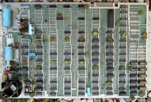
In a previous post I resurrected an Atari ‘Super Breakout’ PCB from 1978. One of the rules of my collection of arcade game boards is that they should all be playable, if they’re working. To that end I try to construct adapters to make the games all compatible with the JAMMA wiring standard, so I can just plug them in to my gaming setup and enjoy them. Usually it’s just a matter of wiring: most game PCBs after about 1980 use similar power and control signals to the later JAMMA standard, but differently wired, so no electronics are needed. Plug time: the Deluxe Arcade JAMMA fingerboard is really handy for making adapters, and I sell them. They’re great value. Buy lots and give them to all your friends.
Super Breakout isn’t such an easy case, though. About the only things which can be wired directly to a modern arcade setup are the coin contacts and start button. Everything else is unusual, starting with the power supplies.
JAMMA wiring provides +5V for powering the main logic, +12V which is usually used by the audio power amplifier, and -5V which is also used on some boards by the sound generation circuitry. Super Breakout’s power input circuitry looks like this.

The circuit appears to expect +10V DC, and a pair of centre-tapped AC supplies, one of 16.5V AC and one of 25V AC. The end result of it all is supplies annoyingly similar to the JAMMA standard: +5V, +12V and -5V, with an extra +20V for the audio power amplifier. I could, of course, just modify the board so that those supplies come straight from the JAMMA wiring, but that would violate another of my rules: no modifications to the original PCBs. Any conversions or adaptations must be done so that the original board, unmodified, can plug into my adapter and thence into a JAMMA connector.
Looking more closely at the circuit diagram, the situation isn’t as bad as it looks. The +10VDC just feeds the input to a regulator which generates the +5V, so it just needs to be a DC voltage large enough to allow the LM323 regulator to do its job. With a regulator this old, this ‘dropout voltage’ is about 3V, so anything from 8V DC upwards should be fine. The lower we can keep this voltage, the less power the regulator will have to dissipate as heat, so the game will run cooler. That’s got to be a good thing.
The 16.5V AC turns out to be used just to power the -5V regulator, so any negative DC voltage greater than about -8V (again allowing for the dropout voltage) will be OK. It doesn’t need to be AC at all. The 25V AC input is simply used to generate the +20V and +12V supplies, so it also doesn’t need to be AC. +20V DC will do fine.
Having figured this lot out, the power supply problem is much less daunting. Converting the +5V and +12V from JAMMA to +8V, +20V and -8V is perfectly manageable.
Various power supply modules are available at low cost from far-eastern suppliers on eBay, including the very popular 150W boost converter module. One of those is just right for converting +5V up to +8V, and a smaller off-the-shelf module can convert +12V up to +20V. Incidentally, though it would seem easier to convert +12V down to +8V, I chose not to do this: the +8V supply to Super Breakout needs to be able to deliver several amps to power all the logic, and the +12V JAMMA supply isn’t rated to handle that sort of load. JAMMA power supplies assume that the lion’s share of the load is on the +5V rail, so that’s where I’ve put it.
Deriving -8V is a bit more tricky. The commonly-available boost converter modules only handle positive voltages, and I can’t play any funny tricks with ground because the +8V and +20V supplies need to share ground with -8V. The answer is a Ćuk converter. A few components hooked on to the switch output of the +20V boost converter can deliver a negative voltage. It’s not regulated, and will depend somewhat on how hard the +20V boost converter is working, but it’s good enough to feed the -5V regulator on the Super Breakout board. Below is a picture of the arrangement. The components inside the dotted pencil outline are on the off-the-shelf boost converter (of the ‘LM2577‘ type commonly available on eBay).

The overall arrangement looks like this, in diagram form:
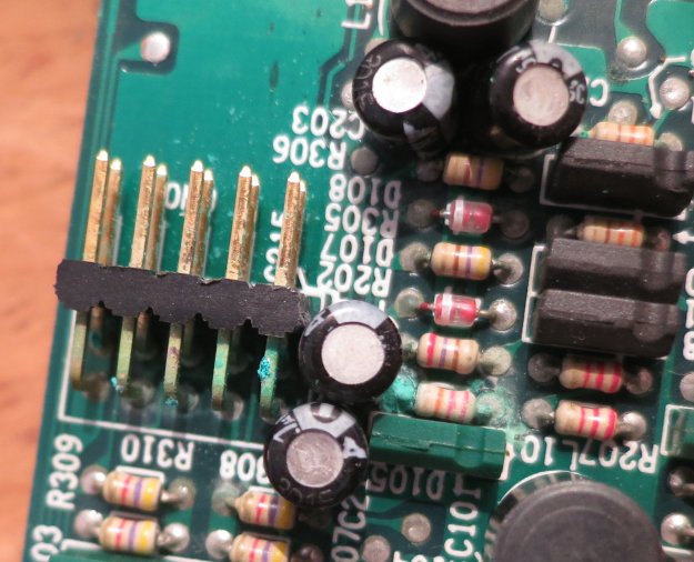
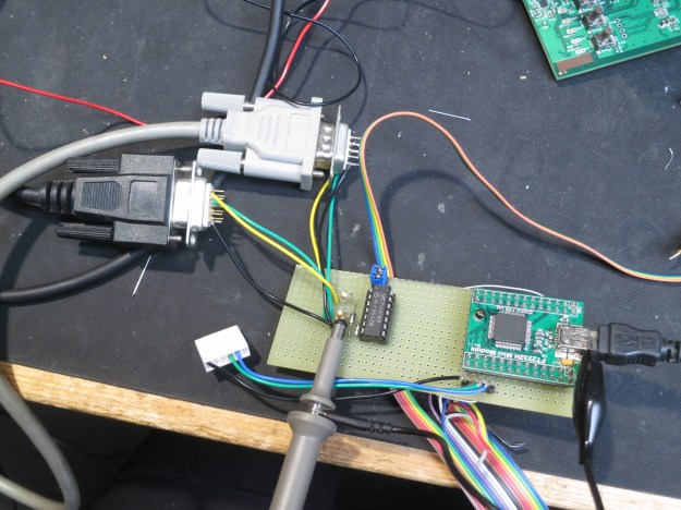
and in real life, it all fits together quite neatly.

The 5V-to-8V boost converter is the large red board at the top. The 12V-to-20V boost converter is the blue board at bottom right, and the components for the Ćuk converter are on the matrix board at bottom left. Note the red wire taking the signal from pin 4 of the LM2577 chip to feed the converter. Game on!