Category Archives: Uncategorized

The BBC Micro linear power supply

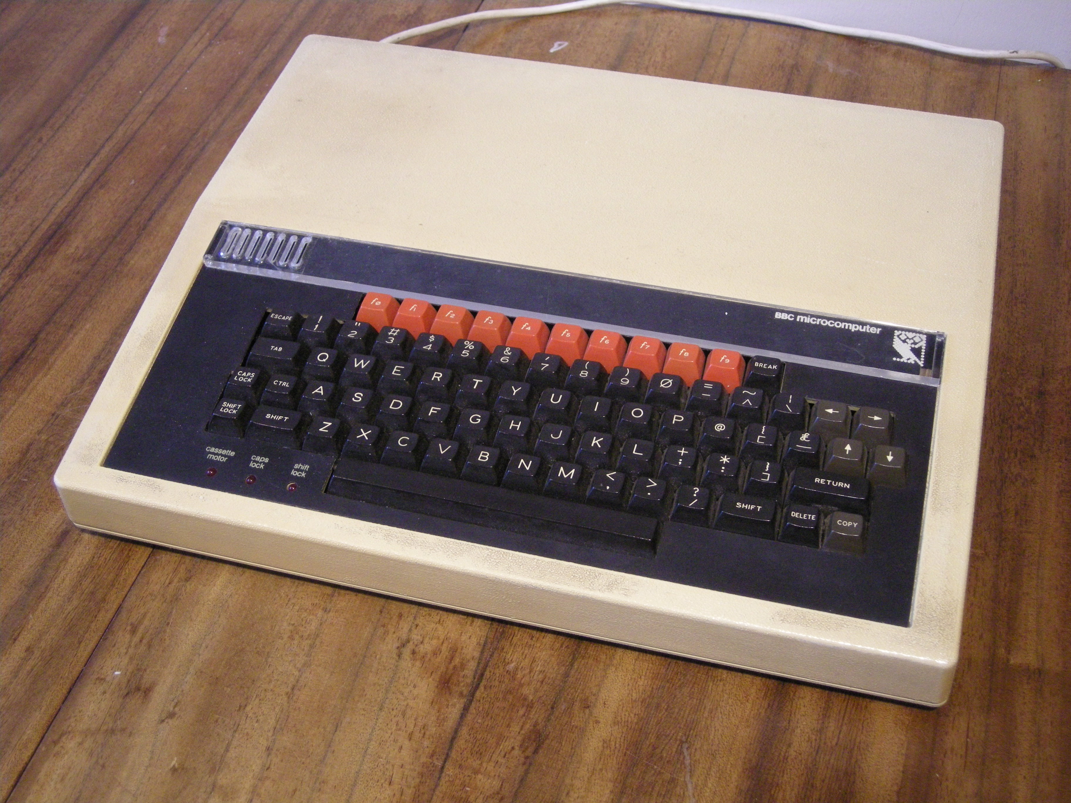
The BBC Micro is the machine that really got me into computing. It was designed by Acorn in a tearing hurry for the BBC Computer Literacy Project in 1981 – see the film Micro Men for a great dramatization of the story. Because it was done in such a rush, some things weren’t quite finished for the early machines. One of those things was the power supply.

Why is the power supply interesting? Well, later BBC Micros had a perfectly normal, reliable switch-mode power supply, not dissimilar to the one in a modern PC. But early ones had a linear power supply, which gained a fearsome reputation for overheating, exploding, and being incompatible with nearly everything. I recently dragged an early, Issue 2, BBC Micro out of the loft and realised it contained this elusive beast, the linear power supply. I thought I’d see what all the fuss was about.

DSCN8929

First things first: does it work? Well, yes. Despite not having been switched on for probably 20 years, it powered up absolutely fine. Boop-beep. No smoke or flames. Good. Time to see what’s inside.

DSCN8933

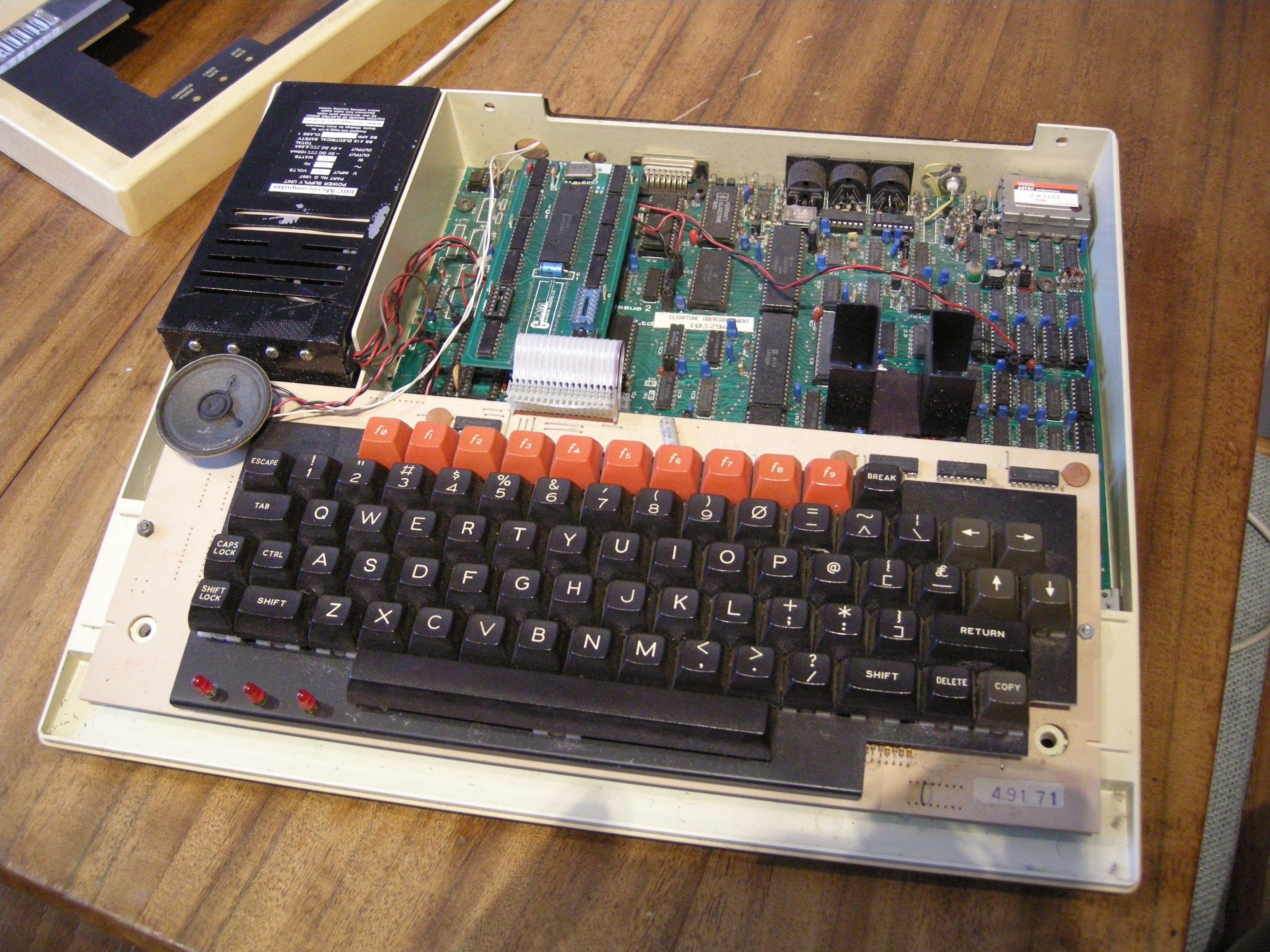
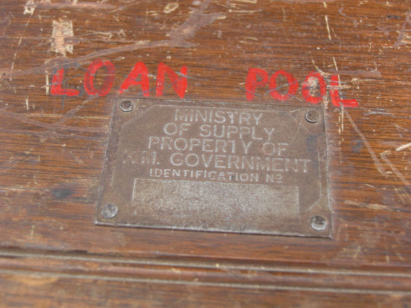
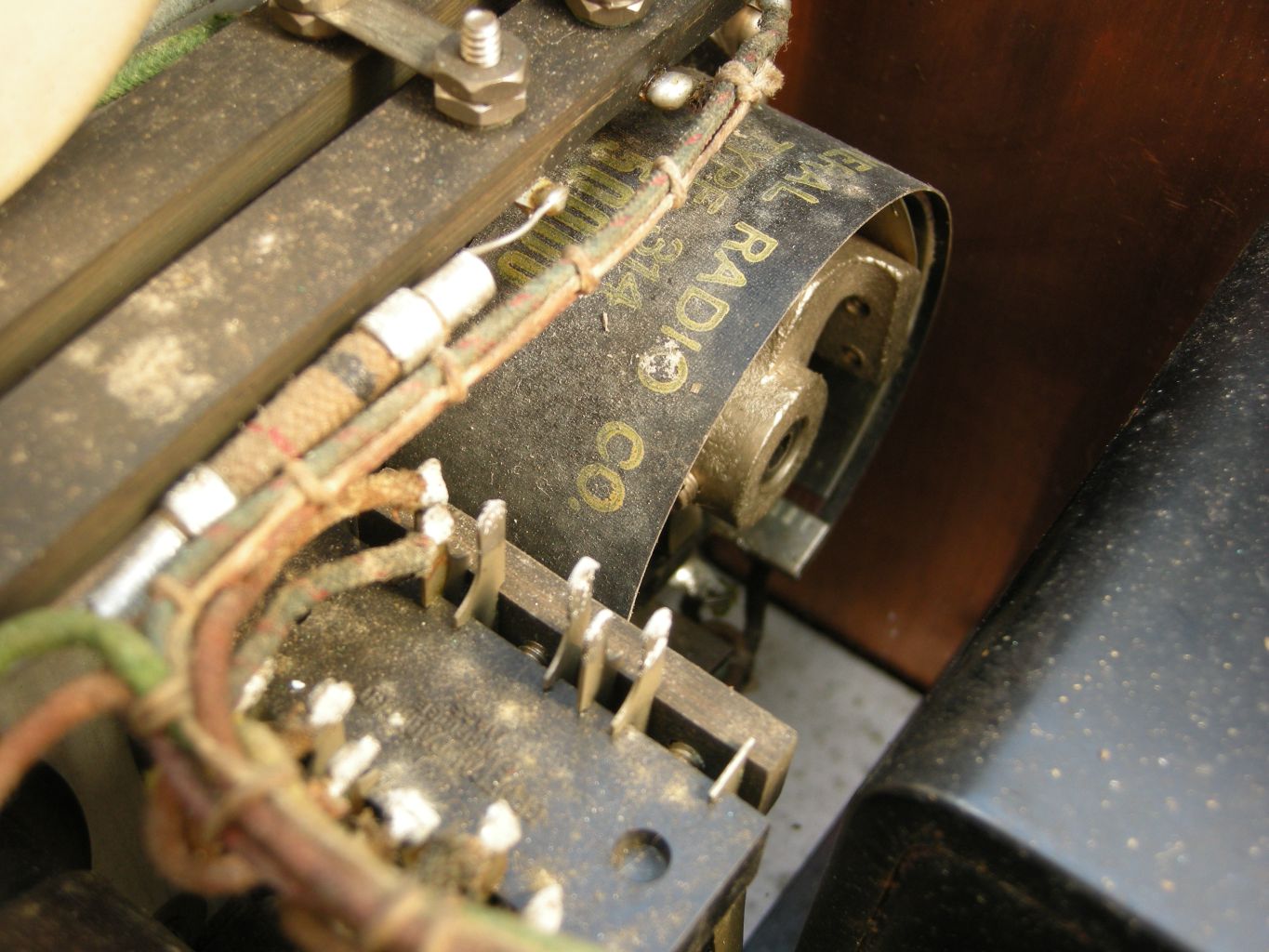
This particular machine started life as a model A, with just 16K of RAM and very little else. However, it got upgraded at some point into a model B, with the full complement of RAM, and has an unusual Opus double-density disc interface in it as well as a couple of extra ROMs including Wordwise, the word processor. That’s the sort of thing that’s supposed to be impossible with a linear power supply. You can see the black box on the left – later power supplies are a gold colour. Here are a couple of closeups of its labels:

DSCN8939  DSCN8931

I took it out and examined it. The first thing I noticed was that it doesn’t really fit very well: there are some odd washers sandwiched between the power supply and the case, and they’ve used nylon screws to fit it, for some reason.

DSCN8942 DSCN8943

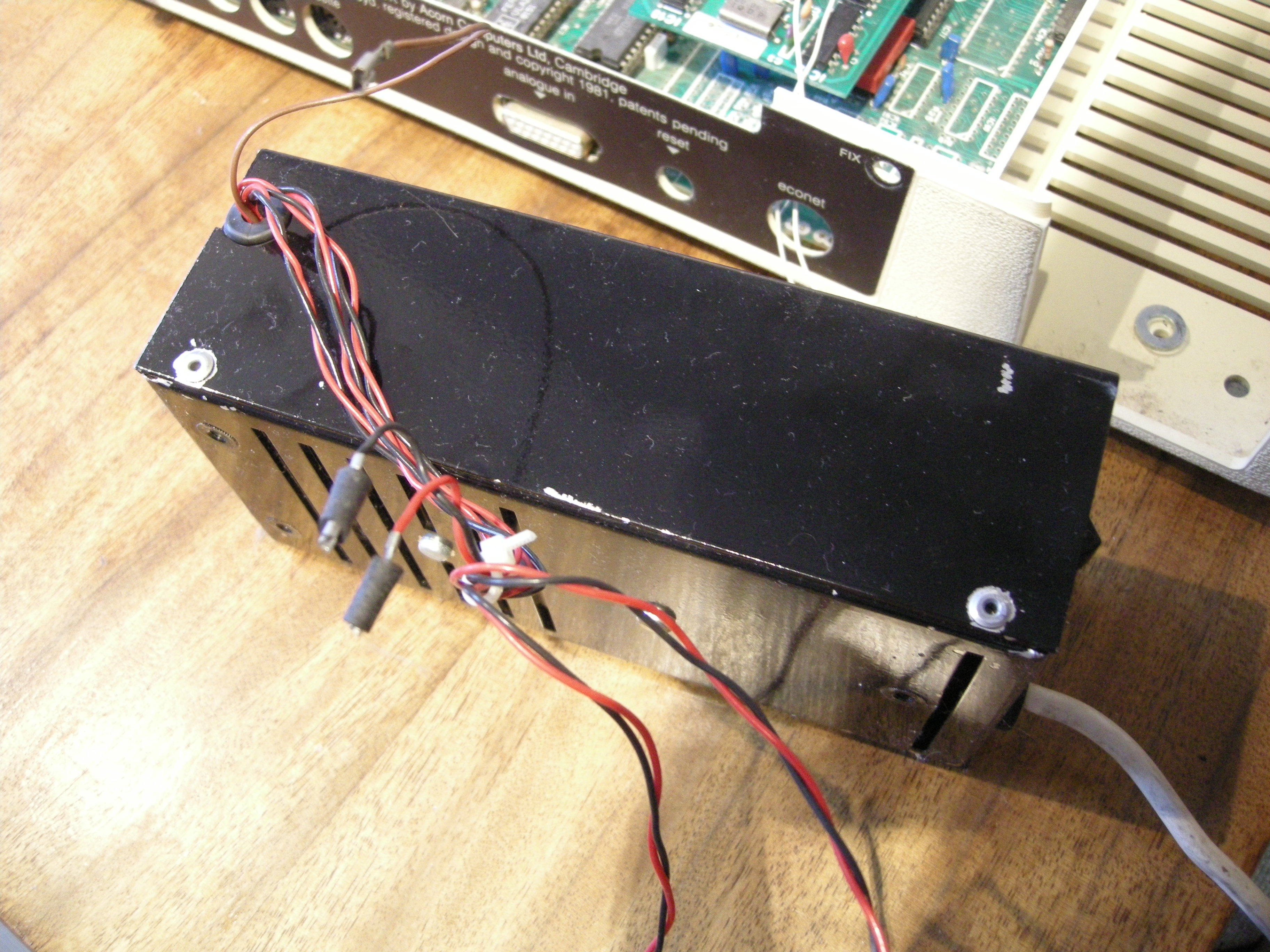
You can probably see from the side view that it’s riveted together. The rivets were quickly dealt with, revealing the insides:

DSCN8948

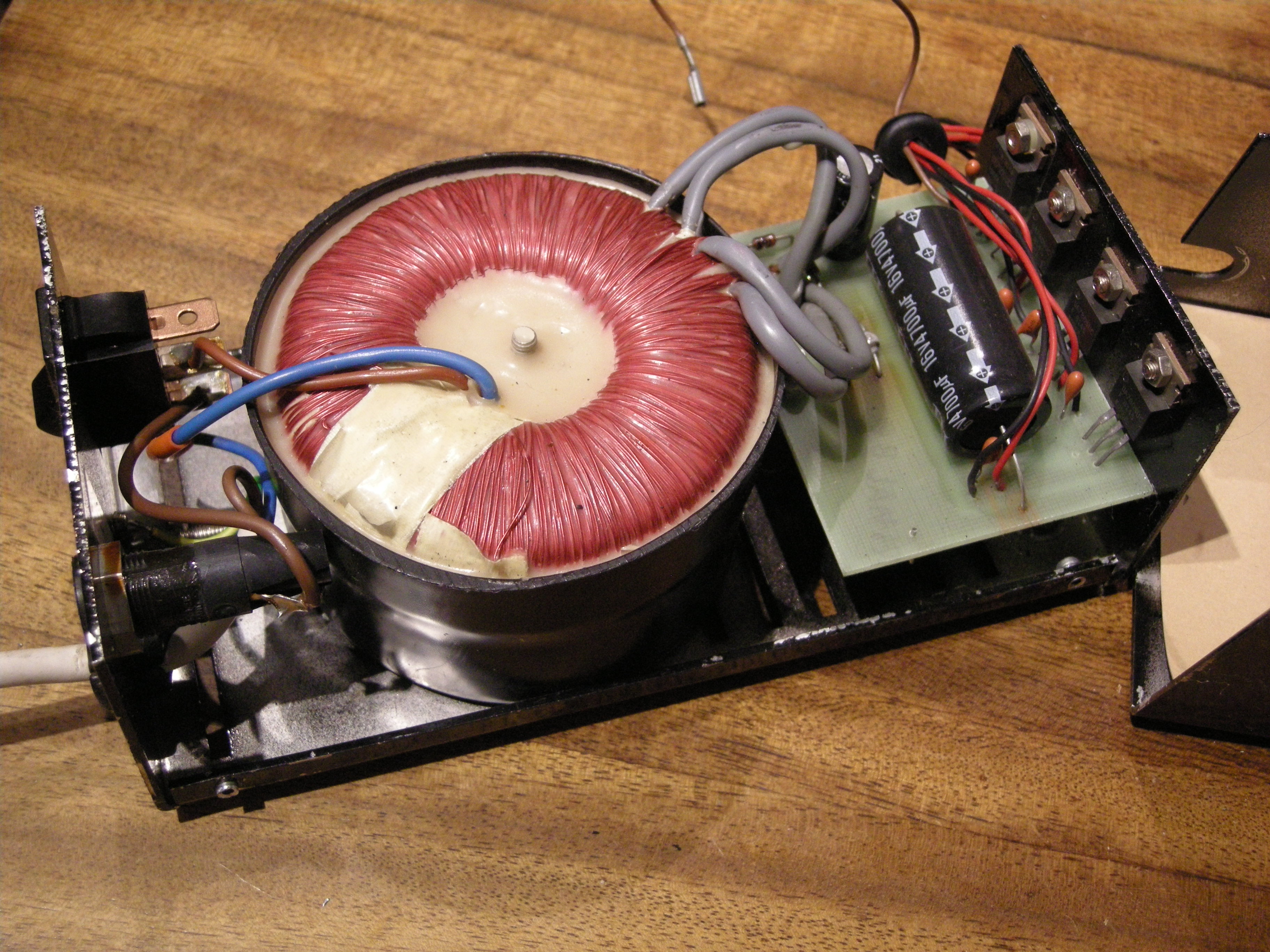
Pretty straightforward stuff: a toroidal transformer, rectifier and smoothing, and a row of regulators. Here are closeups of the circuit board and regulators. Note the little orange tantalum capacitors. I suspect that’s where the reputation for explosions has come from: when used like this, they do tend to fail short-circuit and go off like little fireworks from time to time. These ones, however, are rated at 35V, so with only 5V or 12V across them they should be fairly reliable.

DSCN8950 DSCN8949

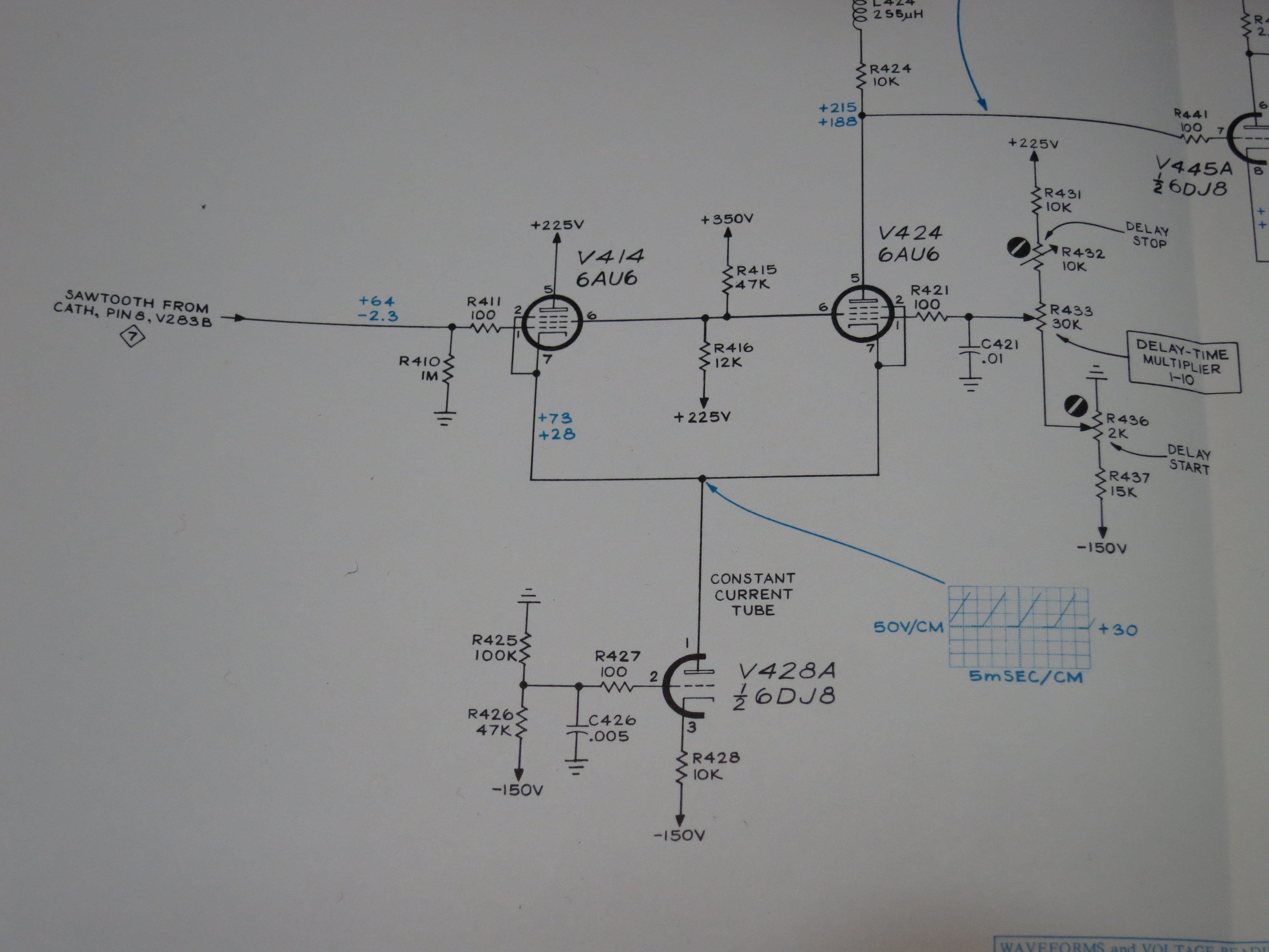
It didn’t take long to trace out the circuit.

DSCN8952

What is interesting is the way the 2.25A output at 5V is achieved. Rather than use one big regulator, they’ve chosen to use three 7805s, rated at 1A each. Three sets of wires leave the power supply and are delivered to three places on the Beeb’s motherboard. There is no connection between the three 5V rails on the motherboard according to my meter. They’re entirely independent. This is good, because it means that the three 7805s won’t end up fighting each other if their output voltages are slightly different.

I took a few measurements while the machine was running. The voltage on the 4700uF smoothing capacitors was 10.5V. The currents delivered by each output were:

VCC1: 0.49A
VCC2: 0.75A
VCC3: 0.84A
-5V: 15mA

I tried removing the disc interface to see what difference that made to the power consumption. It reduced VCC1 to 0.35A and had no other effect.

The total current flowing at 5V is just over 2A, which is sailing fairly close to the wind given that the power supply is only rated at 2.25A. However, nothing in the power supply is under great stress, and I see no reason why it should fail unexpectedly. Unlike a switch-mode supply, it would also be easy to repair. If it was going to be used for a long time, I’d be very tempted to replace the 1uF tantalum capacitors with modern ceramic or electrolytic ones, just because the tantalums do tend to commit suicide randomly with old age.

These machines are now becoming collectable, and early ones like this are worth preserving in their own right. If you’ve got an early Beeb, there’s no reason to fear the linear power supply and replace it. It’s part of the story, and it’s possible to keep it going more or less indefinitely.

Lithium Battery Packaging Overkill

I’ve just received a package of electronic components from RS. The package looked like this (after I’d opened it!):

DSC_0624Ooh! That looks dangerous, especially when you read the label:

DSC_0625So I handled it with care and didn’t set fire to it. Opening it with some trepidation I extracted, carefully, the batteries. They were protected securely inside a pink paper bag. I don’t know if being pink made any difference, though.

DSC_0627Gasp! Three of them! Each nearly half an inch in diameter. I was lucky to get away without serious injury. Imagine the carnage if somehow the parcel had been damaged in transit. There might have been a serious litter hazard as the little plastic bags blew away in the wind.

How does this make any sense? I could probably eat these three batteries without any ill effects. The regulations for shipping batteries have gone mad, which is a pain for those of us who have to work with them.

Oh, and to add insult to injury, they were the wrong sort. I didn’t read the description properly when I ordered them, and I wanted the ones without pins on.


Avometer 8 BLR121 15V battery replacement

The Avometer 8 multimeter has lots of useful ranges, including a special high-resistance range which can measure resistances of up to 20 megohms. This is handy, but it needs a special 15 volt battery. The battery it’s designed for is a BLR121, which was once fairly common but is now dying out. The BLR121 is just about still available but it’s expensive, and since the meter is likely to last a long time I wanted a battery which would also last, and be easy to replace when necessary.

DSCN8944

An old solder reel, a bit of copper pipe, and five common-or-garden lithium coin cells is all it took. The coin cells are CR2032, which are 20mm in diameter, and they fit just neatly inside the solder reel. I cut down the reel to form a tube about 35mm long. The stack of five cells is about 16mm long, so I filled the remaining space with a bit of copper pipe cut to about 22mm long. This is what the assembly looked like:

DSCN8946 DSCN8945

It fitted just neatly into the battery compartment of the meter. The spring contacts are very convenient because you can fit more or less any shape between them!

DSCN8947It works perfectly, and it’s cheap. The CR2032 cells are available for less than 50p each if you shop around, and they have a capacity of around 200mAh. The BLR121 replacements I’ve seen have a capacity of only 40mAh, so the lithium replacement should last about five times longer. Not bad.

Here’s a gratuitous picture of the Avo in use checking the power supply of a BBC Micro.

DSCN8951


Avometer 8 repair

The Avometer 8 is a British electronics icon. For probably half a century it was the standard high-quality multimeter, found in every factory, workshop and laboratory. Though an analogue meter seems like an anachronism in today’s digital world, it’s still useful for some tasks, and there are decades’ worth of service manuals and test procedures which still call for measurements to be made using an Avo. They only stopped making them in 2008 because some parts were no longer available.

DSC_0570

This one was given to me by a colleague who got it as part of a deal when he bought a secondhand broken TV. I’m not making this up, I promise. It (the meter, not the TV) was made in 1964 according to the serial number. It really didn’t work when I got it. It read about 30% low on all ranges, the pointer kept sticking, and it hardly ever returned to the same zero point on the scale. I was on the point of scrapping it, but decided to save it because it’s got stickers on it from the lab I used when I did my degree, and I was encouraged by advice from the people of the UK Vintage Radio forum. I opened it up:

DSC_0566

It’s clear that everything is hand-built, and should be quite serviceable. The problems with this meter seemed to be in the movement itself – the sensitive, fragile coil suspended by precision bearings in a big magnet – rather than the electronics. The movement is so delicate that I was worried about wrecking it rather than fixing it! However, it’s only held in with two screws, so I could take it out and see what needed doing.

DSC_0568

In the picture above, the movement has been taken out and is standing on top of the rest of the meter. With the benefit of a little advice, and a very handy article from the Amateur Radio Relay League in February 1943 called ‘Rejuvenating Old Meters‘, I set to work.

The gap in the magnet in which the coil is suspended was full of tiny iron filings. They’re not supposed to be there. They get in the way, causing the coil and thus the pointer to stick, and they short-circuit the magnetic field, reducing the sensitivity of the meter. I cleaned them out in the recommended way using a little piece of Blu-tack.

The bearings suspending the armature were way out of adjustment: it rattled and caught on the centre pole-piece of the magnet, again making it stick. I adjusted the bearings, centring the hairsprings and the coil in the gap and just taking up the slack so it could move freely. The bearings in the Avo are sprung, so the armature is never quite rigid, but there should be no rattle in it.

Things were looking up, but there was still a problem. The movement wasn’t balanced, so the position of the pointer was very sensitive to which way up the meter was held. The pointer assembly has three little arms, one opposite the pointer and two perpendicular to it, to which it’s possible to add weights to balance the pointer. It’s a very delicate operation. You have to hold your breath while doing it, since the slightest draught sends the pointer swinging wildly. This picture, reproduced from the Rejuvenating Old Meters article, shows how the balancing is done. First, the meter is set to zero while lying horizontally. Then it’s turned to stand vertically. The tail weight is adjusted with the pointer horizontal, and the side weights are adjusted with it vertical.

meterbalance

I used paint applied in droplets with a tiny screwdriver to add weight. You can see it in this closeup of the movement.

DSC_0558

It doesn’t take much – the balance is incredibly sensitive.

Now to test it. The bare movement is supposed to take 37.5μA for full scale deflection. With a power supply and a resistor, I gave it a current of 37.5μA and it worked! I couldn’t tell whether it was exactly right because the naked movement is so sensitive to draughts that the pointer was never quite steady, but it was close enough for me.

I reassembled the meter, sticking the glass (yes, real glass!) back into the case as I went, and was delighted to find that it was now working – no sticking, it returned to zero every time, and was fairly accurate. It read about 1% low, though. That’s within its specification but I thought it could do better. Fortunately the Avo designers made the meter adjustable to fix such errors. There’s a shunt on the magnet which can adjust the magnetic field a little to compensate for the slight loss of magnetism as it ages. It’s the piece of metal with the slot in it, held by one screw, in this photo of the top of the movement.

DSC_0565

A couple of millimetres to the left was all it took, and the Avo now reads correctly to within 0.5%. Not a bad result, considering the only tools required were a screwdriver, a bit of Blu-tack, and some paint. Try that with a faulty digital multimeter!

Sony Xperia P (LT22i) Jelly bean battery drain

I have a Sony Xperia P (LT22i) phone. Sony have recently updated the software for it, so it now runs Android Jellybean. Last week, I plugged the phone into my desktop PC and the Sony software proudly announced that an upgrade was available. The existing (Ice Cream Sandwich) version had some niggly problems, so I thought upgrading was a good idea. Well, I was almost right.

xperiap

The software build it installed was 6.2.A.1.100. The upgrade proceeded without a hitch, but I soon noticed a problem: the phone’s battery life had become hopelessly bad. I used to be about to use it for 24-48 hours without charging, but now it would discharge itself by more than 50% overnight without even being used. That’s useless. Looking at the power management screen, the application using most of the juice was ‘Phone’. Phone? Surely that’s the one application that they must have tested, right? It turns out I wasn’t the only one with this problem. There are forum threads about it on various sites. Look at this one:

http://talk.sonymobile.com/thread/127636?start=0&tstart=0

After much cursing and head-scratching, I managed to fix it, but the fix isn’t very nice. Basically I used the ‘repair my phone’ link in the Sony PC Companion software, which does a factory reset and reinstalls the software. It’s brutal, but effective.

The process goes like this:

  • do a complete backup of the phone using the PC Companion software. Don’t be afraid of the incredibly long time it takes before it actually starts backing anything up.
  • select the ‘Support Zone’, then ‘Phone/Tablet Software Update’, then use the ‘repair my phone/tablet’ link and follow the instructions.
  • when your phone eventually restarts, get it connected to the internet either by Wi-fi or 3G. Add your Google account to it. Don’t try to restore the backup yet: most of it would fail because the apps aren’t installed yet.
  • on a desktop PC, go to play.google.com/apps and log in with your Google account. It should show, under ‘My Apps’, a list of apps previously installed on your phone. Click on them and set them to be installed.
  • the phone should now download and install the apps you’ve selected.
  • when the apps are restored, restore your backup using the PC Companion software. Again, there’s a long delay before anything happens, but it works eventually. Expect a few error messages if there are any apps you had installed before but chose not to put back. They’re harmless.
  • now spend ages getting everything set up the way you liked it before. Sadly the backup doesn’t keep things like your icon layout, wallpaper, notification settings, ring tones and myriad other little things.

This whole process wastes about half a day, in my experience, which is annoying. But at least my phone works properly again and doesn’t drain the battery. I just wish it hadn’t gone wrong in the first place. More testing needed, Sony, please.

BeagleBone Black Debian build from balloonboard.org

The Balloon Board project set out more than a decade ago to produce a high-performance, low-power, open hardware embedded Linux computing platform. It successfully did that, and now thousands of them are in use in all sorts of products all over the world.

One of the major achievements of the project was a build system which could configure, download, patch and build a boot loader, kernel and root filesystem using a relatively simple menu-driven interface. The menu allows the user to select which type of board to build for, and which customisations to apply. These can include custom kernel drivers for a particular application, or a different Linux distribution (Debian and Emdebian are supported). It doesn’t need an especially powerful machine to run on, but can make use of multiple CPU cores to speed up building.

My colleague Nick Bane has recently, in collaboration with Cambridge University Engineering Department, updated the build system so that it can build software for the Raspberry Pi and BeagleBone Black, both of which are somewhat newer hardware than the Balloon Board. This should make it easier to port software and device drivers between the boards without having to start with a completely new development system.

It might also be of interest to developers working with the Raspberry Pi and BeagleBone boards who want a simple, repeatable way to create the necessary software. This is especially important for use in manufactured products, where the process for creating a whole software distribution needs to be well understood.

This page describes my first attempts at building Debian Linux and the kernel for the BeagleBone Black. This is extremely preliminary, and it doesn’t work yet,

Software build options

Get the software:

svn checkout svn://balloonboard.org/balloon/branches/menuconfig2
make menuconfig
  • Mode Expert mode
  • Balloon Board BeagleBone Black
  • Choose which buildroot version to build -> Feb 2013
  • Select kernel version 3.8
  • make kernel-menuconfig
  • Select Kernel Features -> unselect Compile the kernel in Thumb-2 mode
  • make buildroot-menuconfig
  • Package Selection for the target -> Hardware handling -> Misc devices firmwares -> unselect rpi-firmware
  • Hardware handling -> unselect rpi-userland
  • Debian rootfs
  • Select kernel and module installation method -> Build Debian rootfs with kernel modules
make

Create Micro SD card

I used a 2GB card in a USB card reader connected to my Debian Squeeze PC. I created two partitions using fdisk. Partition 1 is a 50MB FAT16 (type 6) partition, and partition 2 is the rest of the card formatted as ext3 (type 83). On my system, the card appeared as /dev/sdc.

sudo mkfs.msdos /dev/sdc1
sudo mkfs.ext3 /dev/sdc2

Copy the files MLO, u-boot.img and uEnv.txt from the BeagleBone USB drive to the FAT partition.

Make uboot image

sudo apt-get install uboot-mkimage

In build/kernel, do

mkimage -A arm -O linux -T kernel -C none -a 0x80008000 -e 0x80008000 -n "Linux" -d ImageBoot uImage

copy uImage into /boot on ext3 partition

copy am335x-boneblack.dtb from /boot on the original BeagleBone Black board into /boot on ext3 partition

The board tries to boot, but kernel dies with a stack dump:

## Booting kernel from Legacy Image at 80007fc0 ...
 Image Name: Linux
 Image Type: ARM Linux Kernel Image (uncompressed)
 Data Size: 8750560 Bytes = 8.3 MiB
 Load Address: 80008000
 Entry Point: 80008000
 Verifying Checksum ... OK
## Flattened Device Tree blob at 80f80000
 Booting using the fdt blob at 0x80f80000
 XIP Kernel Image ... OK
OK
 Using Device Tree in place at 80f80000, end 80f88bac
Starting kernel ...
[ 0.113797] platform 53100000.sham: Cannot lookup hwmod 'sham'
[ 0.114013] platform 53500000.aes: Cannot lookup hwmod 'aes'
[ 0.114792] omap_init_sham: platform not supported
[ 0.114807] omap_init_aes: platform not supported
[ 0.156004] omap2_mbox_probe: platform not supported
[ 0.225933] Unhandled fault: external abort on non-linefetch (0x1028) at 0xf4
[ 0.233938] Internal error: : 1028 [#1] SMP ARM
[ 0.238662] Modules linked in:
[ 0.241861] CPU: 0 Not tainted (3.8.0 #1)
[ 0.246424] PC is at rtc_wait_not_busy+0x14/0x50
[ 0.251241] LR is at omap_rtc_read_time+0x10/0xa4
[ 0.256147] pc : [<c03eee84>] lr : [<c03ef490>] psr: 40000193
[ 0.256147] sp : df053d60 ip : 00000000 fp : c08b0f28
[ 0.268112] r10: df053e18 r9 : c07d31e4 r8 : df2b7000
[ 0.273560] r7 : df2b71c8 r6 : c08b0f28 r5 : c083a9cc r4 : 00000000
[ 0.280365] r3 : f9e3e000 r2 : 00000000 r1 : df053dc4 r0 : df101010
[ 0.287172] Flags: nZcv IRQs off FIQs on Mode SVC_32 ISA ARM Segment kel
[ 0.294880] Control: 10c5387d Table: 80004019 DAC: 00000015
[ 0.300873] Process swapper/0 (pid: 1, stack limit = 0xdf052240)
[ 0.307134] Stack: (0xdf053d60 to 0xdf054000)
[ 0.311684] 3d60: df053dc4 df053dc4 df053dc4 c03ef490 df2b7000 c03ebbd8 c08b0
[ 0.320217] 3d80: df2b7000 c03ec884 00000000 00000000 00000001 df053dc4 00004
[ 0.328746] 3da0: df053df4 c084fcd4 60000113 df2b54b0 00000000 00000000 80000
[ 0.337275] 3dc0: c084fcc4 00000000 00000000 00000000 00000000 00000000 00000
[ 0.345805] 3de0: 00000000 00000000 00000000 c084fe34 c08b0f28 00000000 00000
[ 0.354335] 3e00: 00000000 df101010 c07d31e4 df103640 c08b0f28 c03eba44 dfef0
[ 0.362866] 3e20: 60000113 df101080 df101010 60000113 00000004 60000113 0000c
[ 0.371394] 3e40: df101080 df101000 df101010 c08b0f30 df104cc0 c08b0f2c c07f8
[ 0.379923] 3e60: 00000000 df101044 df2ccb80 c084fe78 c084fdf4 df101010 df104
[ 0.388453] 3e80: c084fdf4 c08af648 c07d31e4 c07ddb14 00000000 c031e1cc c084c
[ 0.396982] 3ea0: df101010 df101044 c084fdf4 c031cf88 df052000 c031d014 00008
[ 0.405510] 3ec0: c084fdf4 c031b66c df045478 df104c80 df052000 df001840 df2c4
[ 0.414040] 3ee0: c0841ea0 c031bf14 c0725ca0 c084fde0 c084fdf4 c084fde0 c0847
[ 0.422570] 3f00: c0860608 c031d5fc c0860608 c084fde0 c07ddb4c 00000007 c086c
[ 0.431102] 3f20: c07ddb4c c07eff94 c07ddb4c c0008858 00000006 00000006 c0780
[ 0.439633] 3f40: 00000000 c07efcac c07eff94 c07ddb4c 000000dd c086060c c07a4
[ 0.448163] 3f60: c0860600 c07ac314 00000006 00000006 c07ac3f0 c0cc8d80 c0570
[ 0.456693] 3f80: c0577e98 00000000 00000000 00000000 00000000 00000000 00004
[ 0.465222] 3fa0: 00000000 00000000 c0577e98 c000e6d8 00000000 00000000 00000
[ 0.473751] 3fc0: 00000000 00000000 00000000 00000000 00000000 00000000 00000
[ 0.482280] 3fe0: 00000000 00000000 00000000 00000000 00000013 00000000 b637d
[ 0.490833] [<c03eee84>] (rtc_wait_not_busy+0x14/0x50) from [<c03ef490>] (om)
[ 0.500636] [<c03ef490>] (omap_rtc_read_time+0x10/0xa4) from [<c03ebbd8>] (_)
[ 0.510257] [<c03ebbd8>] (__rtc_read_time+0x58/0x5c) from [<c03ec884>] (rtc_)
[ 0.519423] [<c03ec884>] (rtc_read_time+0x30/0x48) from [<c03ecad4>] (__rtc_)
[ 0.528773] [<c03ecad4>] (__rtc_read_alarm+0x1c/0x290) from [<c03eba44>] (rt)
[ 0.538858] [<c03eba44>] (rtc_device_register+0x140/0x268) from [<c07d3358>])
[ 0.548850] [<c07d3358>] (omap_rtc_probe+0x160/0x3b8) from [<c031e1cc>] (pla)
[ 0.558576] [<c031e1cc>] (platform_drv_probe+0x1c/0x24) from [<c031cdec>] (d)
[ 0.568657] [<c031cdec>] (driver_probe_device+0x80/0x21c) from [<c031d014>] )
[ 0.578459] [<c031d014>] (__driver_attach+0x8c/0x90) from [<c031b66c>] (bus_)
[ 0.587902] [<c031b66c>] (bus_for_each_dev+0x60/0x8c) from [<c031bf14>] (bus)
[ 0.597431] [<c031bf14>] (bus_add_driver+0x178/0x23c) from [<c031d5fc>] (dri)
[ 0.606963] [<c031d5fc>] (driver_register+0x5c/0x150) from [<c031e58c>] (pla)
[ 0.616948] [<c031e58c>] (platform_driver_probe+0x1c/0xa4) from [<c0008858>])
[ 0.626936] [<c0008858>] (do_one_initcall+0x2c/0x164) from [<c07ac314>] (ker)
[ 0.637019] [<c07ac314>] (kernel_init_freeable+0x108/0x1e4) from [<c0577ea4>)
[ 0.646648] [<c0577ea4>] (kernel_init+0xc/0x164) from [<c000e6d8>] (ret_from)
[ 0.655452] Code: e59f6038 e59f5038 e3a04000 e5963000 (e5d32044)
[ 0.661858] ---[ end trace 33e6cc13d62fdb11 ]---
[ 0.666954] Kernel panic - not syncing: Attempted to kill init! exitcode=0x0b
[ 0.666954]

Tektronix 549 Storage Oscilloscope, part 6

In part 5 I repaired the damage I’d done to the ‘enhance’ feature. The ‘locate’ button was the next problem to solve. It was really sensitive and tended to get stuck in the pressed position.

IMG_5007

Its job is to let the user see where the trace has gone, or where it might appear. It’s necessary because the oscilloscope has dozens of controls – probably more than a hundred – and if any of them isn’t set right, the usual result is a blank screen. The locate button helps by squashing the trace in from all four sides and cranking the brightness up to maximum, so you can see whereabouts the beam is pointing. Here’s a picture of a normal trace (a video output from a BBC micro, as it happens) and what it looks like if I move its vertical position way up off the screen and press ‘locate’. You can see that a squashed version of the trace appears near the top of the screen, so I know I should move it down to see it properly.

IMG_4999 IMG_5001

The 549 has an extra feature, though. Because it’s a split-screen storage oscilloscope, it’s expected that it will often be used in single-sweep mode: waiting for a trigger signal, then recording a trace once, then stopping so you can see it. While it’s waiting for the trigger, there’s nothing to see on the screen. It would be helpful to have some idea where the trace will appear when the sweep starts, to make sure it will actually be captured.

Tektronix, typically, thought of this problem. The locate button behaves differently when either of the ‘store’ buttons is pressed. In this mode it simply moves the beam into a special non-storage area on the left of the screen and turns up the brightness but leaves its vertical position unchanged. In this way you can see where the trace will start when it triggers, but without trampling on the storage area. Neat. Here’s a picture of the same video waveform as above, correctly positioned but with the timebase in single-sweep mode, storage enabled, and ‘locate’ pressed. You can see the shape of the trace on the left, out of the storage area.

IMG_5004

Of course, to achieve this, the locate button has several contacts affecting various parts of the circuit. It’s buried deep inside the scope behind the front panel, and is a pain to get at. I managed to remove it and found that one of the brass contacts which also provides the spring action had fractured and actually fell off when I touched it. That would explain why it was getting stuck.

Img_4684

I considered replacing the switch with something else, or a relay, but realised that by dismantling the existing switch (it was strung together like a kebab with two screws), rearranging the contacts a bit and soldering a couple of them together, I could repair it. It took a bit of experimenting with the paxolin spacers until the action was right and all the contacts did what they were supposed to, but it was a success. After reinstalling the switch, which involved some tricky soldering at close quarters, it all worked as it should.

Img_4687

Time for the finishing touches. I gave the case a good clean and got out the tinsnips to make a new cover for the EHT compartment because it was missing. I had to guess what it looked like from photos, but I added an insulating sheet of plastic on the inside to reduce the risk of a high-voltage flashover from the transformer pins or anywhere else.

DSC_0517

DSC_0519

With a quick clean of the case and knobs and a replacement mains lead (the old one was perished and cracked and wouldn’t pass a PAT test) this magnificent machine is ready for use once again.

Tektronix 549 Storage Oscilloscope, part 5

In part 4, we’d got the delayed timebase working thanks to swapping out a pair of 6AU6 valves. But there was still something not working, and it was all my fault. I’d killed the ‘enhance’ feature.

IMG_4690

The 549 is special because it’s capable of capturing an event which takes place in less than a microsecond, and storing it so a human viewer, or a film camera, has time to see it. There’s no digital memory or computer here: the storage is done in the cathode ray tube, directly on the screen. By an amazing feat of electrostatic trickery, it’s possible to put the screen into a mode in which electrons hitting the screen at a point will ‘bump’ the phosphor screen at that point into a different state, and it’ll stay like that – it’s a bistable phosphor. Then, by gently sprinkling electrons all over the phosphor from a flood electron gun, the bits which have changed state continue to glow. In this way, as the electron beam sweeps across the screen tracing out the waveform, it can leave behind a visible trail. It’s possible to erase the trail later by winding up the power of the flood gun for a moment, and bumping the phosphor back into its normal state.

This is some pretty advanced physics, and it’s very analogue: lots of bits of metal inside the tube at precisely-controlled voltages throwing electrons around in a high-speed game of ping-pong so they end up in the right places, with the right energy, at the right time. Tektronix, forever at the bleeding edge, wanted to extract the last possible bit of performance from this finely-tuned and expensive system. As the electrons hit the phosphor, it takes a certain number of them to get it to change state. If the beam is sweeping too quickly, there isn’t time for that to happen, and so the trace doesn’t get recorded. However, it turns out that if the whole screen gets a bit of a ‘kick’ from the flood gun before recording starts, it gets more sensitive for a moment, so it can record faster traces. The specifications quote a writing speed of 5cm per microsecond, which is pretty swift. I reckon it’s roughly equivalent to 100 megasamples per second in a digital oscilloscope. Digital scopes took another 20 years to get that good. The 549 was released before Sgt Pepper’s Lonely Hearts Club Band.

This ‘kick’ to wake the screen up is provided by the enhance feature. A couple of transistors generate a precisely-timed pulse just before the sweep to get the screen ready and poised to catch the electrons. Or, at least, that’s what should happen. It turns out that if a clumsy repairer accidentally short-circuits the 500 volt power supply to the input of the enhance circuit, it dies.

IMG_4660

I killed D1134, Q1135, Q1145 and D1146 in one swift move. The damage stopped there because the next component in line is a valve, which shrugged off such a minor trifle as an accidental half a kilovolt.

The diodes were simple to replace. I used 1N4148s. The transistors looked uncritical enough, and I put a couple of 2N3704s in. But the circuit didn’t work. No pulse came out, and no enhancement happened. I looked again at the design, and it seems that the gain hFE of the transistors, especially Q1135, is critical.

The transistor Q1135 is biased by R1133 and the ‘enhance width’ control R1132. Normally, it should be switched on, and when a negative-going pulse from the trace flyback blanking arrives via C1131 on the left, it should switch off for a moment and generate a pulse. However, the gain of my replacement 2N3904 was too high. The current glowing through R1132 and R1133 was enough to keep it switched on all the time, even when the blanking pulse arrived. Result: no ‘enhance’ pulse output.

The manual says that the original transistor is equivalent to a 2N918, which has a gain of about 50. I didn’t have any of those, and they’re long obsolete. But there’s another half a dozen of them on this board doing other jobs, so maybe I could swap some from there and use my newer transistors for another job. A quick look at the circuit revealed this:

Img_4661

Here are two transistors, Q1033 and Q1043, just being emitter followers from the erase controls. It really wouldn’t matter what their gain was, as long as it was enough. A quick swap and…success! Both erase and enhance worked as intended.

It’s very handy that the transistors in this machine are all in sockets. Interestingly, the old ones look like they’re in TO92 packages:

Img_4663

But their pinout is the opposite way round to modern transistors, which have to sit facing the wrong way in the socket with their legs bent.

Img_4662


So far so good. There are still a few problems to sort out, though. The ‘trace locate’ button is ridiculously sensitive, so you barely have to breathe near the scope and the trace shrinks into a little rectangle in the middle of the screen, which is annoying, and the whole thing is filthy dirty. Timebase A’s triggering seems a bit jittery at high speeds, too.


Tektronix 549 Storage Oscilloscope, part 4

In part 3, the scope was working, with a trace that seemed to do the right things. But the delayed timebase was dead. It’s a handy feature that effectively lets you select a part of the waveform on the screen and zoom in to magnify it, and in today’s digital world it seems almost inconceivable that it was possible to do such things with analogue electronics.  Mind you, it takes quite a lot of analogue electronics to achieve it, especially with valves. The 549 contained an outrageous 53 valves when I counted them. In the photo below, the swung-out panel on the right is basically devoted to the delayed timebase.

IMG_4654

There’s a part of the circuit called the ‘delay pickoff’ which is responsible for selecting which part of timebase B’s sweep to magnify or, more accurately, when to trigger timebase A. It contains a comparator, which compares the sweep voltage as the beam scans across the screen with another voltage, which you set by turning the ‘delay multiplier’ knob on the front panel. When the two match, it sets a flip-flop, which triggers timebase A. In this way, you can choose where on the screen to start the timebase by turning the knob. Handy.

I started probing around with another oscilloscope to see what was going on, or not going on. The circuit diagram in the manual is full of helpful voltage readings and waveforms so you can see what should be there at various points.

IMG_4656In this case, I found that there was a nice sweep sawtooth on the grid of V414 at the left hand side of the diagram, but instead of a sweep on pin 1 of V428A (the blue waveform), I just had about -120V. The grid of V428A was also at about -125V, when it should be held at -100V by R425 and R426. Aha, I thought, R425 has gone high in value! These old carbon resistors do that. So I checked it – no, it’s fine. Then it must be V428A that’s faulty! I even proved it by removing it from its socket, and the voltage at pin 2 returned to -100V. I borrowed a known good 6DJ8 from elsewhere and triumphantly fitted it. Switch on and…no change. Hmm.

If V414 and V424 both have 225V on their anodes and -120V on their cathodes, they’re clearly not conducting much, or they’d probably have melted. I swung open the panel that they’re mounted on and had a look at them. V424 wasn’t glowing, and felt cold! I gave it a wiggle in its socket and it started to glow, and immediately the voltage at its cathode went up to about +30V. Found the problem! But still there was no sawtooth waveform there, just a voltage which varied as I turned the delay multiplier control.

I carefully cleaned the pins and sockets of V414 and V424 but it didn’t help. I thought I’d try swapping them over, to see if anything changed. For no particularly sensible reason, I did it with the power switched on, and I’m glad I did: as I put the second one back into its socket, I noticed purple flashes from inside it! That’s not supposed to happen. One of the 6AU6s is very sick. Here’s the guilty party.

IMG_4657

I borrowed a 6AU6 from another scope, and there was an improvement: the delayed timebase started to work, but the range was all wrong. It would start the delay half way across the screen, and it was impossible to adjust it properly. I replaced the other 6AU6 as well and it worked much better. I was able to adjust the delay start and stop controls so each notch on the delay multiplier knob corresponded to one division on the screen, just as they are supposed to. Here’s a picture of the delayed timebase working. It’s in ‘B intensified by A’ mode, and you can see the brighter section of trace.

IMG_4658

Time to go shopping for a pair of 6AU6s.