Category Archives: Projects

Orange Livebox 2.0, port forwarding and NAT loopback

For several years, I’ve been running a small server (a Sheevaplug, as it happens) connected to my home broadband connection. It’s not running anything public, but it’s simply handy to have somewhere I can log in to and do things with from anywhere on the internet. It used to be connected via Virgin Media’s cable broadband service, using an Apple Time Capsule as a router, and a dynamic DNS service to handle the name lookup, and it all worked just fine. I could access my server from computers both inside and outside the house.

Recently I moved house, and the new place has broadband provided by Telekomunikacja Polska masquerading as Orange. Their broadband deal comes with its own router which also provides the VoIP phone service as well as having something to do with the TV. It’s a Livebox 2.0. It would probably be possible to set up a different router to do the same job, but the thought of getting the VoIP stuff to work is too awful to contemplate.

livebox-2

The Livebox 2.0 is a fairly flexible box, and I managed to set it up to forward traffic on one port to my server. The server has a little script which updates its dynamic DNS entry, and that did exactly what it said on the tin. I could log in to the server from elsewhere on the internet. But could I connect to the server’s public IP address from inside the house? No way. The router just reported ‘no route to host’. This was annoying. I have various things set up on my laptop which assume they’ll be able to connect to my server, and to have those not work when I’m at home would be a real pain.

The problem seemed to be that the Livebox didn’t want to route traffic from the internal network, where my laptop was, to its external IP address. Reading Wikipedia on NAT, it turns out that this is a feature called NAT loopback. I didn’t even know it was possible for routers not to support it, but I learn something every day. The Orange Livebox 2.0 won’t do it (and yes, I played exhaustively with all the security/firewalling/port forwarding options).

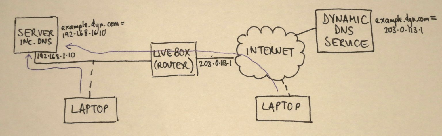
This called for a workaround. My server has a DNS entry with a dynamic DNS provider. Let’s call it server.dyn.com (it’s not, actually). This resolves to whatever the external IP address of my router happens to be – let’s say 203.0.113.1. From inside my home network, the router makes a mess of handling traffic to 203.0.113.1 so I can’t contact it. However, I have control of DNS on the home network: it’s one of the services on my Sheevaplug. I know that ‘spoofing’ DNS entries is bad practice, but I’m going to do it anyway. I can add entries to my local DNS server which make server.dyn.com look up to 192.168.1.10, the local address of the server. The laptop won’t know the difference, but it’ll be able to contact the server. And outside the home network, there’s no chance of anyone, including me, accidentally contacting my DNS server because there’s no way for traffic to get to it. Here’s a picture.

Img_6117s

I use bind9 as my internal DNS server. I added a section to /etc/bind/named.conf.local:

zone "dyn.com" {
  type master;
  file "/etc/bind/db.dyn.com";
};

and then created another file /etc/bind/db.dyn.com:

$ORIGIN .
$TTL 604800 ; 1 week
dyn.com IN SOA localhost. root.localhost. (
  2009060801 ; serial
  604800 ; refresh (1 week)
  86400 ; retry (1 day)
  2419200 ; expire (4 weeks)
  604800 ; minimum (1 week)
  )
  NS sheevaplug
$ORIGIN dyn.com
example A 192.168.1.10

It worked! At home, example.dyn.com resolves to 192.168.1.10, and out on the internet, it resolves to 203.0.113.1. I think it’s far from perfect – the timing settings on my dyn.com record probably need to be made shorter, so that the laptop doesn’t hang on to them when I leave home, and this setup means that all other subdomains of dyn.com don’t work, but it’s good enough for me for now. Maybe it’ll be helpful for you too.

Embedded serial port debugging on the cheap

I do a lot of electronics design and debugging. It’s how I make my living. Most of the things I work on involve embedded computers of one sort or another talking to various peripherals. It could be an 8-bit microcontroller sending data to a simple data logger, or a sophisticated 32-bit Linux system communicating with a wireless modem. Many of these connections involve asynchronous serial ports. If something goes wrong, as it usually does, It’s really useful to be able to see what’s going on with the communications. Here’s a picture of the sort of thing I’m dealing with. It’s a board I designed which contains a load of power electronics as well as a microcontroller and a USB data logger which talk to each other using a serial connection. Note the 175A fuse next to the USB connector!

DSC_0511

Monitoring a serial port on a PC is relatively easy, but the ones I deal with are separate from the PC, stuck on some circuit board on the workbench or buried inside a piece of equipment. To complicate matters, I need to monitor both directions of traffic at the same time, and have some idea of what order things happened in. There are many protocol analyser tools out there which will do all sorts of clever things, but it’s hard to justify them for small projects.

Faced with a such problem to solve recently, I put together a cheap and simple system which allows a developer to monitor both directions of an embedded serial port simultaneously, and have a record of which end transmitted what, when. It consists of a software tool and a bit of hardware.

Software

The software is a simple tool I wrote in C. It compiles and runs under Linux. Given the names of two devices, it opens both of them. It waits for a character on either of them and displays it on the screen in hexadecimal and ASCII. Each device has a separate column. Every time data arrives from the other device, it starts a new line. Each line is timestamped. In this way, it produces a dump of the conversation between the two devices, and it’s clear what order things happened in, and who said what.

It has one other handy feature: it has a ‘-l’ for (‘live’) command line option. In this mode, it will update the display every time a character arrives so you can see occasional data as it happens. This is great for monitoring things like keystrokes. This mode involves a whole load of backspacing and overprinting on the display, so it’s not really suitable if you want to record the output of the tool for later examination. The non-live mode is better for that – it outputs data only when it has a complete line.

Here’s an example session using the software.

hdump2Here you can see that I used stty to set the baud rate of two serial devices attached to the PC. Then I ran the tool (provisionally called hdump2). You can see the data after that. The timestamps are on the left, followed by hexadecimal representations of the data, then the ASCII version. In this case we’re watching the initialisation of a Vinculum USB host controller. The data isn’t guaranteed to be in exactly the right order character-for-character, since it’s had to travel from two serial ports through the operating system, but it’s good enough for debugging.

The source is available to download here:

hdump2-1.0-source.tar.gz

To build it:

tar xzf hdump2-1.0-source.tar.gz
make

It’s free software, licensed under the GNU General Public License.

Hardware

The hardware can be any pair of serial ports suitable to connect to the device under test, but I made a little module which makes it easier. It’s based on an FTDI FT2232H Mini Module. In fact, that’s all it is! There are just a couple of wire links to configure its power supplies and bring the receive pin of each of its two serial ports out to a connector. There’s a load of spare space on my board which I intend to use eventually to fit various useful connectors and buffers to hook up to the different serial port standards I come across.

DSC_0516

The wiring looks like this:

  • Join pin CN3-1 to CN3-3
  • Join pin CN2-1 to CN2-11 and CN3-12
  • serial input 1 is on CN2-10
  • serial input 2 is on CN3-25
  • input ground is on CN3-2 and CN3-4

When plugged in to a PC, two devices (typically /dev/ttyUSB0 and /dev/ttyUSB1, assuming you don’t have any other USB serial ports attached) appear. They can be used as the device arguments to the tool.

Do let me know if any of this is useful to you, or if you have comments or improvements to suggest or contribute.

Bubble Development Board – progress

Having now had the Bubble Development Boards for a few days, I’ve tested a few more features.

Both JTAG sockets (Xilinx 14-pin and ARM 20-pin) work with their respective dongles.

The Ethernet adapter, a Wiznet W5100, is showing signs of life. If I plug an Ethernet cable into it, the ‘link’, ‘full duplex’ and speed indicator LEDs come on. Frequently the ‘link’ LED blinks continuously along with the Rx LED. I don’t know why, though searching on the web indicates that the W5100 can be fussy about the choice of transformer it’s used with, and sometimes about what kind of hub it’s plugged into – apparenly the automatic MDI/MDI-X negotiation can get confused. The tests were done with a TP-Link TL-SF1005D switch and I haven’t tried any other. Sometimes, though, the link will settle down to a steady state, then I see the Tx and Rx LEDs doing sensible things.

DSC_0453

The W5100 chip is wired to the Samosa bus with very simple address decoding so that it should appear every 4 bytes across the whole 256-byte Samosa address range. Manually poking and peeking its registers from the Bubble board’s boot loader gave sensible results, and I even managed to get it to try and send a packet, the Tx LED blinking reassuringly.

Recent Linux kernels have a driver for the W5100. I tried kernel version 3.7.1 which has already been patched for the Bubble board. The existing drivers expect the chip to be I/O or memory mapped, which is not the case on this board because it’s on the Samosa bus. The Samosa bus is accessed using its own function calls inside the kernel. I patched the driver, and had to undo one or two assumptions made in the code about memory access, and the results are promising: the chip is found correctly, interface eth0 appears, and it even sends packets from the DHCP client attempting to get itself an address. However, the first attempt to send a packet results in an error:

NETDEV WATCHDOG: eth0 (w5100): transmit queue 0 timed out

and a stack trace, though the kernel carries on running. It seems that the Ethernet chip’s interrupts are not making it into the kernel. This turns out to be due to the offending interrupt line not being connected to anything in the Bubble board’s CPLD, so I’ll have to fix that next. That needs the Xilinx programming dongle which I haven’t got with me at the moment.

Bubble Development Board – first prototypes received

A couple of days ago I received the first examples of the Bubble Development Board and started testing them.

DSC_0420

Much to my joy, the board fits neatly into a low-cost plastic case from Farnell, part number 1526699. With front and rear panels suitably cut out, it should be well protected and easy to connect things to.

DSC_0421

But does it work? Well, yes, largely. Here are the results so far.

  • Power: the LEDs (green for +5V input, orange for VDD_IO from the Bubble) come on and the Bubble board starts up reliably.
  • Reset button: does what it says on the tin.
  • Serial port: console works.
  • USB host: tested to work with a memory stick and a USB-to-Ethernet adapter.
  • USB slave: working. USB networking connection successfully established to a desktop PC as documented at http://www.balloonboard.org/balloonwiki/USBNetworking.
  • Audio: output works, straight into a pair of headphones, and quality seems good with no unpleasant background noises. Haven’t tried input yet.
  • HDMI: the Bubble board I was using was set up to drive an LCD panel, but by installing fbset and fiddling around with the settings (making them roughly 800×600, 60Hz) I managed to get a display on a monitor connected to the HDMI port. However, the image tends to disappear every few seconds and then come back again with some flickering, so something’s not quite right. I tried another monitor via an HDMI-DVI cable with the same result.
  • Micro SD socket: not working yet. The kernel reports an error during boot and /dev/mmc* devices don’t appear. I’ve noticed that other implementations of the SD card socket from Bubble have pullup resistors on all the data and clock lines which I neglected to put on this board. This might be an easy fix because the wiring looks right.
  • JTAG, Samosa, Raspberry Pi header, Ethernet: not tested yet.

Here’s another picture with the Bubble board turned over so you can see what’s on it.

DSC_0422

How to Get a Real Serial Port – PCI Express under Linux

serialport

I do a lot of hardware and software development on things with embedded processors, ranging from little 8-bit Atmel chips to big 32-bit ARM-based things like the Balloon Board. Often the systems they’re built in to don’t have much of a display or keyboard, so getting information in and out of them for testing and debugging purposes is tricky. One thing that really helps is a good old-fashioned serial port. Pretty much every embedded processor has some kind of serial port on it, and they’re generally very easy to use from software so can be got working very early in the development process.

In order to make use of a serial port, you need another one to connect it to. This used to be easy: they used to be ubiquitous on desktop and laptop PCs. However, in the last 10 years they’ve gradually died out and been replaced by USB to serial adapters. Though such adapters are cheap and readily available, I’ve had loads of problems with them. Since they’re easily detached, they often seem to go missing, or get left in toolboxes and attached to projects. Some of the ones I’ve used also sometimes seem to get themselves in a mess and start turning my data into junk until they’re unplugged and reinserted. This is not helpful.

usb-serial

It can also be hard to predict how the serial port will be identified when it’s plugged in: under Windows, it gets a COM port number, but which number it gets depends on how many other such devices have ever been plugged into that machine and even into which USB socket, so setting debugging software up to find the one you want is impossible. Under Linux the same problem exists but with an extra feature: if you have a terminal program watching a serial port, then accidentally unplug it and plug it back in again, the program carries on as if nothing has happened but you don’t see any output . That’s because the operating system thinks that the old port is still in use even though it’s not there any more, and allocates a new, available number when it’s plugged back in, so /dev/ttyUSB0 magically becomes /dev/ttyUSB1. Even restarting your terminal program doesn’t work, because it’s still going to look at the old number. You can reconfigure the terminal program to look at the new one, but then you’ll find that if you shut everything down and restart it, the USB serial port will have moved back to /dev/ttyUSB0. The only way out is to stop the program, unplug the adapter again, plug it back in and restart the program. This is a serious pain.

I recently had the chance to do something about this problem in my own workshop. I was configuring a new Linux PC for the workbench, and discovered, to my great joy, a little-documented feature on the shiny new Gigabyte GA-Z77N-WIFI motherboard: a serial port! Tucked away on a little white connector, there it was, forgotten and unloved. All it needed was a cable to bring it to the outside world, and it worked. It turns up as COM1 under Windows and /dev/ttyS0 under Linux, and it’s always there, can’t be unplugged, and never changes its number. Wonderful.

If one serial port is good, more must be better. The motherboard has a PCI Express slot on it, intended for a turbo-nutter graphics card which this machine didn’t need. I found a PCI Express serial port card, similar to the PEX4S553 from Startech.com which looked like it would do the trick. Actually I had it lying around because I’d fitted it to a Mac Pro a couple of years ago, but it never worked properly in the Mac.

startech-card

I put it in the machine and switched on. Would it work? Typing lspci revealed that it was there, and was working, so were the ports usable?

ls /dev/ttyS*
ttyS0    ttyS1    ttyS2    ttyS3

Not bad, but why only four? There’s the one on the motherboard, plus four on the card, so that should be five, right? Well, to cut a long story short, after a bit of web research, I found that the standard serial port driver in the Linux kernel only looks for four serial ports as standard, but responds to a kernel command line parameter to make it look for more (or indeed less). Experimentally rebooting and manually editing the kernel command line in grub to add

8250.nr_uarts=5

to the end of it worked! I had all five ports, and they all did what they should. To make the change permanent, I edited /etc/default/grub to add 8250.nr_uarts=5 to the end of the GRUB_CMDLINE_LINUX_DEFAULT parameter, and ran update-grub. Now all five ports turn up every time I switch the machine on, and I’m a happy developer. By the way, I’m running Debian Linux 6.0 (squeezy) with kernel version 3.2.something from backports, but the kernel version won’t make any difference – this stuff is all ancient history.

It remained only to tidy up the wiring. The ports on the Startech card appear on 10-pin headers. The wiring on these is simple: pin 1 on the header goes to pin 1 on the 9-pin D connector, pin 2 to pin 2, and so on. Pin 10 isn’t used. However, the way the pins are numbered differs between the headers and the D connectors: the headers are numbered on alternate sides, like a street, so one side is 1/3/5/7/9 and the other is 2/4/6/8/10. The D connectors are numbered 1-5 on the top row and 6-9 on the bottom row.

I had a load of serial port breakout cables in the bottom of my PC parts box, left over from the early 90s. I found that many of them were wired straight-through, like this:

DSC_0359[1]

which is wrong for the Startech card. I had to rewire them to look like this:
:DSC_0362[1] DSC_0361[1]

according to the correct pin numbering, and then they worked. The card fitted neatly in the back of the machine:

DSC_0366[1]and, as a finishing touch, I did a ‘case mod’ to mount two of the serial ports on the unused 3.5″ floppy drive blanking plate:

DSC_0365[1]Notice how they’re labelled, so I always know which is which! It’s a very practical arrangement for the workbench, having reliable serial ports always at hand. The other two are round the back, and will probably be used less frequently.

Henelec PA25 power amplifier and MU442 power supply

Over on the Vintage Radio Forum, someone asked recently about the Henelec PA25 power amplifier module. The PA25 was produced by Henry’s Radio of London in around 1970. Since I have a pair of them, including the associated MU442 power unit, I’ve documented them here.

Here are a couple of general views. The MU442 has sockets for mains in, signal input (3-pin DIN) and speaker outputs (DIN again). There are also a pair of power supply fuses. Connections to the PA25 modules are via wiring harnesses with edge connectors.

Img_3997

IMG_3999


Here’s what one of the modules looks like. It’s a sandwich of a PCB and heatsink.


IMG_4000


This is what’s on the PCB…


IMG_4003

…and on the heatsink…

IMG_4004


…and the back of the PCB.

IMG_4001


The heatsink has a pretty label on it:

Img_4005


This is the MU442.

Img_4006


Inside, there’s a mains transformer with 2x 22VAC secondary windings, four BYZ13N rectifier diodes in stud-mounted packages, and a pair of smoothing capacitors.

Img_4007


I drew out the schematic diagram of the circuit. It’s made with silicon transistors and is pretty conventional, I think,

PA25_Schematic


Here’s a PDF file of it: PA25_Schematic


Using a 32.768kHz external crystal with Atmel XMEGA microcontroller RTC

I’ve just brought up a project using an Atmel XMEGA series microcontroller which uses an external 32.768kHz crystal to run its real time clock (RTC). I had some trouble getting it to work, but now I’ve found the recipe, thought I’d share it in case it’s useful to anyone.

DSC_0308

In principle, you’re supposed to enable the crystal oscillator and then wait until the XOSCRDY bit is set in the OSC.STATUS register, indicating that the oscillator has started up. My problem was that the oscillator seemed to be running, with a healthy-looking waveform at the XTAL1/TOSC1 pin, but the ready bit never got set.

DSC_0309

It turns out that the order of initialising the registers is important. You have to set XOSCCTRL first, to configure the oscillator, then enable it in CTRL, then wait for it to be ready. The code looks like this

OSC.XOSCCTRL= OSC_XOSCSEL_32KHz_gc;
OSC.CTRL|=OSC_XOSCEN_bm;
while(!(OSC.STATUS&OSC_XOSCRDY_bm));

That’s what worked for me. I’m using AVR Studio 6 and AVRGCC version 3.4.1.95.

Bubble Development Board V1.0

I’ve just got V1.0 of a development board for the ‘Bubble’ embedded ARM module ready for manufacture, and will hopefully have prototypes soon.

BubbleDevBoard1.0

It’s designed to make the Bubble board easy to work with, and brings out various useful connectors:

  • JTAG ports compatible with Xilinx (14-pin) and ARM (20-pin) dongle pinouts
  • Serial port for the console
  • USB host, for memory sticks, keyboards and whatever else
  • USB slave, for mass storage or USB networking
  • Micro SD card
  • HDMI for monitor connection
  • Ethernet
  • Stereo analogue audio in/out
  • Raspberry-Pi compatible expansion connector with I2C, SPI and GPIO

It’s all powered from a Micro USB connector which should take a standard mobile phone charger, and is designed to sit neatly in a low-cost plastic box for protection.

Everything except the Ethernet port is already supported by Linux on the Bubble board, though making the HDMI port work will involve some fiddling with the LCD output timings. The Ethernet port is based on the Wiznet W5100 chip, which is popular in the embedded community and is supported by recent Linux kernels.