Category Archives: Projects

Servicing a Fluke 12 Multimeter

One of my most-used tools on the workbench is my Fluke ’12’ multimeter. I’ve had it almost 20 years, and it’s my favourite meter because it was clearly designed by someone who had to fix things. It’s rugged, especially in its bright yellow holster, and has so many thoughtful features: it has big buttons and a switch, instead of a rotary knob, so it’s easy to use with one hand. It autoranges quickly and reliably. In continuity and resistance modes, it automatically switches to measuring voltage if it detects one, so you don’t need to worry about changing ranges when debugging things. It doesn’t have fiddly extra features. It doesn’t even have a current range, because it would make no sense: measuring current usually involves breaking a circuit, which you can’t easily do when working on a circuit board. It switches itself off when unused for half an hour or so, saving the battery.

Img_0007

It’s been completely reliable apart from needing a new set of test leads last year (for the first time). However, recently the big, chunky buttons had become reluctant to respond, and needed firmer and firmer presses until they didn’t work at all. That meant I was stuck measuring either DC voltage or continuity. Time to pull it apart and see what’s wrong.

Removing the test leads and holster, then taking out the four screws, reveals the view you get when changing the battery. I’m sure Dave at EEVBlog, master of the multimeter teardown, would approve. Lots of chunky components and very solid construction.

Img_0008

The PCB is held in by the plastic clips at the top and sides. Easing them back lets it and the plastic frame underneath it come out:

Img_0010

The black plastic internal frame (under the PCB in this photo) is marked as being made of polycarbonate, so it’s very strong. None of that high-impact polystyrene rubbish. It’s nice that the membrane for the buttons bears against the frame, not straight against the PCB. This is nice industrial design.

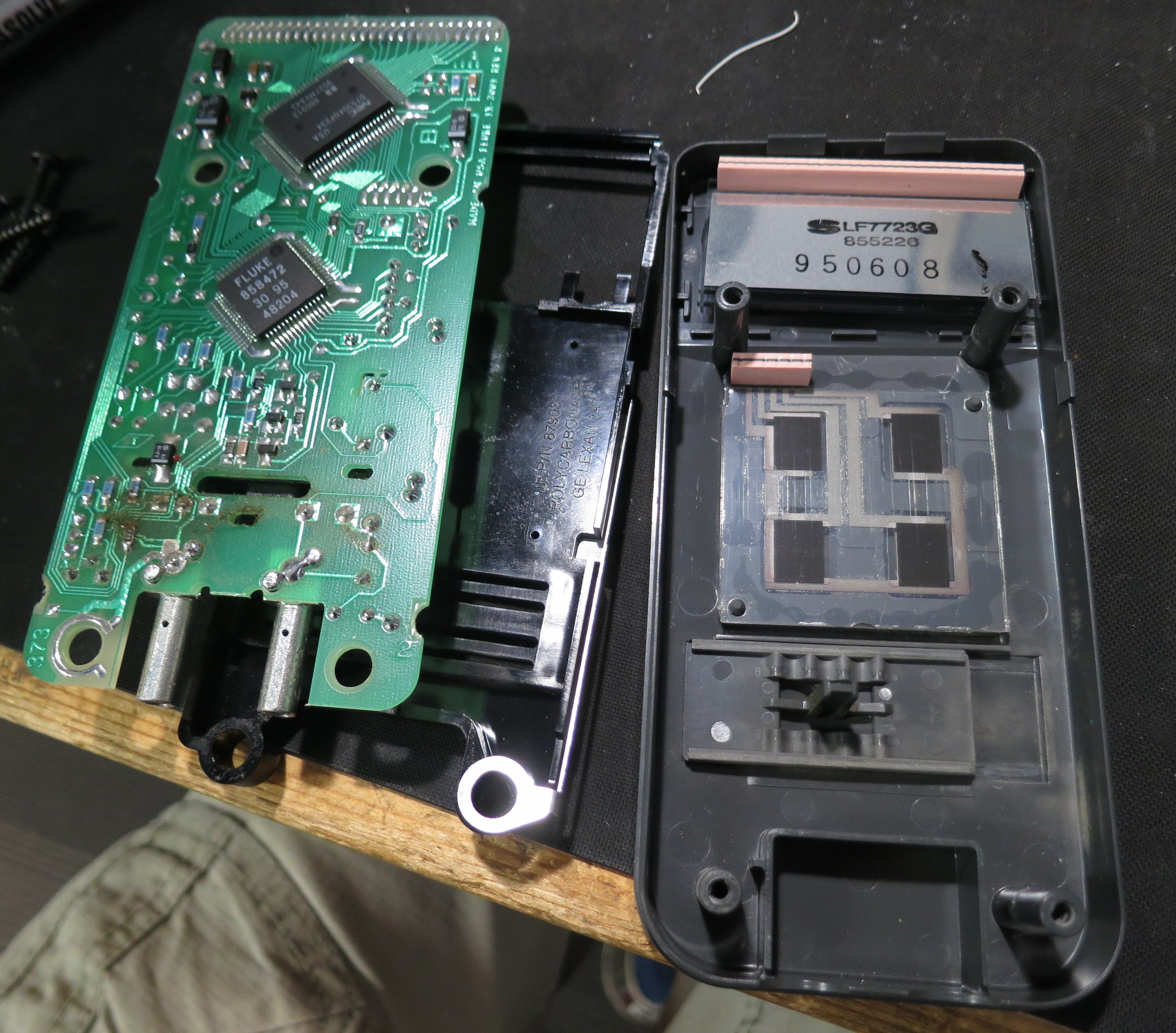
The button membrane is connected by a zebra strip to the PCB. The PCB itself looks nice and clean, and the zebra strip is OK, but the contacts on the membrane look tarnished.

Img_0012

I wanted to test the membrane using the continuity check function of my trusty Fluke 12…oh, hang on, it’s in pieces. Break out the equally trusty Avo 8.

Img_0013

The membrane itself works fine. I cleaned up the contacts using DeoxIT D5 on a piece of paper. I also cleaned all the plastic parts, including the holster, in the office sink with washing-up liquid. Here’s the result, showing resistance mode to prove that the buttons work.

Img_0014

Looking good, working as well as it did when new, and ready for the next 20 years.

Calculating days of the week on a Propeller

I’m doing a project using a Parallax Propeller microcontroller at the moment. It’s like a normal microcontroller, but psychedelic. Eight cores, peripherals defined almost entirely in software, and primarily programmed in a cunning language called Spin. Spin is a very efficient interpreted language and makes it possible to squeeze a lot into the Propeller’s meagre 32K of RAM.

The project has a real-time clock maintained by an off-the-shelf clock chip, but this application needs to know the day of the week as well. Of course, I can get the user to set the day of the week when they set the clock, but it’s unintuitive to have to set it manually, and this thing is supposed to be easy to use.

IMG_0006

I looked in to algorithms for calculating the day of the week given a year, month and date. There are loads of them. The Wikipedia page has lots, and this Stackoverflow page has a load of useful suggestions. There was one particularly simple one which appeared in both places, credited to Tomohiko Sakamoto on the comp.lang.c Usenet newsgroup in 1993. I don’t care about the theory behind the algorithm, I just want it to work and to be simple to program in Spin. The original is in C and looks like this:

dayofweek(y, m, d)	/* 1 <= m <= 12,  y > 1752 (in the U.K.) */
    {
        static int t[] = {0, 3, 2, 5, 0, 3, 5, 1, 4, 6, 2, 4};
        y -= m < 3;
        return (y + y/4 - y/100 + y/400 + t[m-1] + d) % 7;
    }

My Spin version looks like this:

DAT
 dayTable BYTE 0, 3, 2, 5, 0, 3, 5, 1, 4, 6, 2, 4

PRI decFromBCD(n)
 return (n&$f)+10*((n&$f0)>>4)

PRI calcDayFromDate | y
 y := decFromBCD(year) + 2000
 if month < 3
   y--

 day := (y + (y/4) - (y/100) + (y/400)
       + dayTable[decFromBCD(month)-1]
       + decFromBCD(date)) // 7

Mine looks more complex, and the one reason for that is that the clock chip maintains its counts in BCD (binary-coded decimal) rather than straight decimal. There might be a cunning way to modify the algorithm to take BCD values directly, but I took the easy route of implementing a function which converts an 8-bit BCD value into decimal.

The code assumes the presence of three variables: year (0 to 99, starting at the year 2000), month (1 to 12) and date (1 to 31) and sets a variable day in the range 0 to 6, where 0 is Sunday.

When implementing the clock in your project, don’t forget to compensate for the leap second tonight.

Solidlights new LED upgrade

The first Solidlights products to be sold used the Lumileds Luxeon III LEDs, which were state of the art back in 2003. Technology has moved on since then, however, and modern LEDs are much more efficient – they produce a lot more light for the same amount of electricity. Though I’m no longer actively developing Solidlights, I occasionally tinker with upgrades to the ones I use regularly.

For a year or so now I’ve been using a modified Solidlights 1203D dynamo light fitted with Cree XP-G2 LEDs. Getting the best from them requires modifications to the lenses, too, but it’s worth it: the theoretical maximum light output from each LED is 488 lumens, whereas the old Luxeon III could only manage about 80 lumens. I’ve done the modification informally for a couple of customers, too, and they’ve been happy with it.

xpg2

There’s been more interest recently, so I’ve made this upgrade available in the Solidlights on-line shop. It’s listed as part number 99002 under ‘service and repairs’.

Sideways RAM for BBC Micro Model B+

There’s an excellent article by Mark at RetroClinic on adding 32K of Sideways RAM to a BBC Micro with just a couple of track cuts and wires. I’ve performed it on a BBC Model B, in order to replace a Solidisk SWR which never worked reliably even when it was new, and the modification works well. However, I wanted to do it on the BBC B+ I use in the office, and the details are slightly different.

The first thing to note is that the B+’s sideways ROM sockets are conveniently already wired to support 32K chips (27256 EPROMs). There is a row of links to the left of the ROM sockets which select whether each socket is configured for a 16K chip or 32K chip. Each link just selects whether pin 27 (A14 on 27256, /PGM on 2764 and 27128) is tied to +5V or connected to the bottom bit of the ROMSEL register IC45. If the link is to the left, pin 27 is tied high, and if it’s to the right, it’s an address bit. To be honest I can’t see any reason not to leave them all to the right all the time, since pulling /PGM low on 2764 and 27128 chips seems to have no effect other than disabling the chip. However, on my B+ they were all set to the left by default.

The layout of the parts on the board is:

    +------+ +------+ +------+
S19 |      | |      | |      |
S18 | IC62 | | IC68 | | IC71 |
S15 | ROM  | | ROM  | | OS & |
S12 | banks| | banks| | bank |
S11 | 8/9  | | A/B  | | 1/F  |
S9  |      | |      | | BASIC|
    | (S15)| | (S18)| | (S19)|
    +------+ +------+ +------+
    +------+ +------+ +------+
    |      | |      | |      |
    | IC35 | | IC44 | | IC57 |
    | ROM  | | ROM  | | ROM  |
    | banks| | banks| | banks|
    | 2/3  | | 4/5  | | 6/7  |
    |      | |      | |      |
    | (S9) | | (S11)| | (S12)|
    +------+ +------+ +------+

Note that S19 (for IC71) behaves a bit differently. IC71 is always the OS ROM, which is not a sideways ROM, but can be a sideways ROM (in bank 1 or bank F) as well. If S19 is placed to the right, IC71 should have the OS in the top 16K and a sideways ROM image, conventionally BASIC, in the bottom 16K. Which bank this ROM image ends up in depends on the setting of S13. If S13 is set ‘north’, the lower half of IC71 appears in bank 1. If it’s ‘south’, it appears in bank F. Normally bank F is convenient for BASIC.

The key ingredient of the sideways RAM upgrade is to provide a write enable signal to the RAM chip. This isn’t normally present on ROMs because it makes no sense to write to a ROM. The RetroClinic upgrade takes a write signal from IC77 pin 8. This is the write strobe for the uPD7002 ADC and the 8271 floppy disc controller. The corresponding signal still exists in the B+, and is used by the ADC and the 1770 floppy disc controller. It comes from IC27 pin 6, however, which is conveniently close to the ROM sockets.

However, there’s an annoying difference between a 27256 32K EPROM and a 62256 32K RAM. The EPROM has A14 on pin 27, but the RAM has A14 on pin 1 and /WE, the write enable signal, on pin 27.

On the Model B, it’s not hard to cut the tracks to pins 1 and 27 and solder wires on the bottom of the board. However on the B+, the tracks to those pins are on the top of the board, mostly concealed by the socket, and are a royal pain to get to. I could have desoldered the socket, done the modifications and put it back, but that was relatively risky and a lot of effort. I decided to just take pins 1 and 27 of my RAM chip outside the socket and run a wire from pin 27 to IC27 pin 6, and pin 1 to IC45 pin 14 (the source of the address line), on the top of the board. Here’s what it looked like.

DSC_1094

My final discovery was that the Sideways RAM utilities are provided by the 1770 DFS ROM. My B+, however, only had DFS version 2.10, which doesn’t include them. I programmed a ROM with DFS version 2.26, and took the opportunity to shuffle the existing ROMs into 32K chips to save sockets.

This done, the SRAM commands were now available, but the Sideways RAM wouldn’t work. I’d put my RAM chip in socket IC57, which is banks 6 and 7. It seems that the B+ and DFS SRAM utilities only understand about Sideways RAM in the banks which the B+128 would have it: banks 0, 1, C and D, exactly the banks which are not covered by the ROM sockets. Doh!

I needed to move my RAM chip to appear in banks 0 and 1. This was easily accomplished by moving pin 20 outside the socket and soldering a wire from it to IC46 pin 15. IC46 is the address decoder for the ROM sockets, and pin 15 is its /0 output.

Now, when switched on, the machine shows ‘Acorn OS 96K’ (cute!) instead of its previous ‘Acorn OS 64K’, and the *SRLOAD command works to load images into banks 0 and 1.

Img_8121s

In summary, to add 32K of Sideways RAM to a BBC B+ 64K:

  • Move S12 into its right-hand position
  • Bend pins 1, 20 and 27 of a 62256 RAM chip so they fall outside the socket
  • Put the chip with bent pins into socket IC57
  • Solder a wire from pin 1 to IC45 pin 14
  • Solder a wire from pin 20 to IC46 pin 15
  • Solder a wire from pin 27 to IC27 pin 6
  • Make sure your DFS is version 2.26

Now you have Sideways RAM in banks 0 and 1. Job done.

IMG_8120

Dealing with Shellshock on Debian Squeeze for ARM

Today’s announcement of the Shellshock Bash vulnerability had me worried. I run lots of Debian Linux systems, and they’re not all the latest version. Many are still Debian Squeeze (version 6) which no longer gets security updates as standard. That’s my fault, of course, and I should have upgraded, but I haven’t. Yet. Now I’m more motivated to do it. However, upgrading to Debian Wheezy (version 7) isn’t something I wanted to do in a hurry, especially on remote machines.

Debian have thought of people like me, and there is a ‘Long Term Support‘ option for Debian Squeeze, which is great, and includes the necessary security update to Bash. The trouble is, it only supports i386 and amd64 processors, and the machines I’m worried about are ARM (specifically armel) ones.

I was left with one option: build the new Bash from source. Fortunately, Debian Squeeze LTS has the source available, so I was able to do this. Here’s how. This might be useful to other Debian ARM users who are none too fastidious about keeping up to date.

I added the line

deb-src http://http.debian.net/debian squeeze-lts main contrib non-free

to /etc/apt/sources.list, and did

apt-get update
apt-get source bash

which fetched the source code. Then I had to build it.

cd bash-4.1
dpkg-buildpackage -b -us -uc

This complained bitterly about a load of missing dependencies, which I dealt with:

sudo apt-get install autoconf autotools-dev bison libncurses5-dev debhelper texi2html gettext sharutils texlive-latex-base ghostscript

which was a royal pain due to lack of disc space. Beware, these packages want about 180MB of disc space (plus about 80MB for the package downloads) so might need some care on a small system. I started by installing packages individually, doing ‘apt-get clean’ after each one, but texlive-latex-base is an absolute monster and I had to do some filesystem reshuffling to get it to install. I hope you don’t have to.

During the build (repeating the dpkg-buildpackage command above) the patch for ‘CVE-2014-6271‘ was mentioned, which was reassuring. The actual build process took a while – about half an hour on a 1GHz-ish ARM chip (a SheevaPlug).

The build completed successfully, so I was able to install the new package:

cd ..
sudo dpkg -i bash_4.1-3+deb6u1_armel.deb

and then start a new shell and try the test:

env X="() { :;} ; echo busted" `which bash` -c "echo completed"

on a ‘broken’ version of Bash, this will print

busted
completed

but on a fixed one, it prints

/bin/bash: warning: X: ignoring function definition attempt
/bin/bash: error importing function definition for `X'
completed

which is the right answer, and means that the vulnerability is patched. It worked!

I hear that the fix isn’t complete, though, so more work may be required later.

That syncing feeling: classic arcade games that won’t stay still

I’ve got a collection of classic arcade games from the ‘golden era’ of the early 1980s. They’re not the whole wooden cabinets with flickering lights and cigarette burns, but just the circuit boards from inside. They are easy to store and easy to plug in to a joystick and monitor to play.

However, some of them have always been a bit tricky to see. The monitor I use, a spiffy Microvitec bought surplus from Display Electronics in 1990, has fantastic picture quality but is a bit fussy about its input signal. Specifically, it seems to expect that the sync pulses – the bits of the signal which indicate where lines and pictures start – must conform more-or-less closely to broadcast standards. Unfortunately, the people who designed the old video games weren’t too worried about complying with standards. The result is that, on my monitor, some games tend to flicker and roll, or require very finnicky adjustment of the controls.

There’s loads of information about what video sync pulses are supposed to look like on the web.  This link has plenty of detail. However, the important things here turned out to be that the horizontal sync pulses should be fairly close to 4.7 microseconds long, and the vertical sync pulses should be pretty much three lines, or 192 microseconds, long.

I compared the outputs of various games – one which had never given problems (Mr Do’s Castle) with three which were troublesome (Phoenix, Pleiads and Q*Bert). The results were interesting. Here’s the vertical sync period from Mr Do’s Castle:

mrdocslv

In all the scope pictures, the red trace is the sync output from the game, and the blue line is the vertical sync from my electronics which I’m just using to trigger the scope at the right time.

In this case, the narrow red pulses are the horizontal sync pulses, and the broad area between the dotted lines is the vertical sync pulse. It’s six lines, or about 386 microseconds, wide, which seems to be good enough to keep the monitor happy.

Examining Pleiads and Phoenix, which have the same video electronics, here’s the horizontal sync pulse:

pleiadsh

Oh dear, It’s only 3 microseconds wide when it ought to be 4.7. And the vertical sync pulse?

pleiadsv

It’s a full eight lines wide, or more than 500 microseconds. Those numbers are way off what the monitor is expecting. The result is that the monitor refuses to give a stable picture, which makes playing the game very tricky:

Img_7793

Looking at Q*Bert, its horizontal sync pulses are nearly three times as wide as they should be, at 12.6 microseconds:

qberth

and Q*Bert’s vertical sync pulse looks like this:

qbertf

It lasts more than a millisecond! That’s miles off. The effect on the picture looks like this:

Img_7782

That’s as stable as I could get it. Notice how the left hand side (which is actually the top – the monitor is rotated 90 degrees)  is curved and wobbly. It was fairly hard to adjust the monitor to get the picture stable enough to take a photo.

There are solutions to these problems which involve modifying the game boards themselves, but I didn’t want to do that. I think they’re interesting historical artefacts (even the bootleg ones) and I try to keep them as original as possible. I wanted to fix the sync problems outside the board.

After a bit of experimenting, I came up with a little circuit which regenerates the sync pulses to be a bit more standard.

Img_7778

Untangling the rat’s-nest of wires, the schematic diagram looks like this:

syncfix-schematic

The circuit is simple and cheap, using two standard TTL logic ICs. It ought to work with 74HC series chips as well, but some of the resistor values might need changing. The diode is any common-or-garden signal diode: a 1N4148 or 1N914 is fine. It works like this.

  • IC1B is a monostable which triggers on every sync pulse, generating a pulse 4.7 microseconds long. These become the new horizontal sync pulses.
  • IC2B combined with D1, R3 and C3 form a sync separator which triggers the monostable in IC1C only on sync pulses which are longer than about 40 microseconds.
  • IC1C is a monostable which generates vertical sync pulses about 200 microseconds long.
  • IC2E combines the new horizontal and vertical sync pulses into a new sync signal.

The output isn’t what you might call broadcast standard, but it’s close enough to make the monitor happy. I’ve tried it on a few games and it works even on games which the monitor was happy with before. Here’s the results from Pleiads:

pleiadsc

Nice horizontal sync pulses, with a vertical pulse 193 microseconds long. There are a few extra pulses around but the monitor doesn’t seem to mind.

Img_7783

The results from Q*Bert are also good, though the vertical sync looks even more odd:

qbertc

The vertical sync pulse is a sensible length, but there’s a long pause after it before the horizontal pulses start again. That doesn’t bother the monitor, though, and all the wobbles have gone away. Here’s the test setup in use.

Img_7777Sorry about the mess, but at least the display on the monitor is tidy. Mission accomplished.

Parameters in Altium Designer

I use Altium Designer a lot for schematic capture and PCB layout: drawing electronic circuits, in other words. It has a handy feature called ‘Parameters’ which should make it easy to add a piece of data, for example a version number or the author’s name, to a project and have it appear on all of the documents which form part of that project. I’ve always had trouble getting it to work, but I’ve finally cracked it and I’m writing down my findings here so that I don’t forget them. Other people may find it useful too.

V1_0

1. It’s possible to set parameters on a project and then refer to them in documents, but if there is a parameter in the document with the same name, it will hide the project parameter.

For example, all schematic documents have a ‘Revision’ parameter by default. If I set a ‘Revision’ parameter for the project, it won’t appear in any of the documents because the document ‘Revision’ parameter hides it. If I choose a new name which isn’t already used in the documents, like ‘ProjectRevision’, it does appear in the document.

2. In schematic documents, parameters are referred to using the equal sign:

=ProjectRevision

In PCB documents, they’re referred to using a dot:

.ProjectRevision

It’s bonkers, but it’s true.

Here’s my recipe for getting a version number to appear on both schematic documents and the PCB layout.

  1. Set your version number on the project using Project -> Project Options -> Parameters. Call it something which isn’t one of the default document parameters. I use ProjectRevision.
  2. In schematic sheets, use =ProjectRevision in text strings to call up the version number.
  3. In PCB sheets, use .ProjectRevision in text strings to show the version number.
  4. Make sure ‘Convert Special Strings’ is switched on in both schematic and PCB editors otherwise you won’t see the version number.

For the schematic editor, select Tools -> Preferences -> Schematic -> Graphical Editing and make sure ‘Convert Special Strings’ is ticked.

For the PCB editor, select Design -> Board Layers and Colours -> View Options and make sure ‘Convert Special Strings’ is ticked.

That’s it. Using parameters has made managing my Altium projects quicker and easier.

SD memory card access from an Atmel AVR microcontroller using sd-reader

I’ve recently had a need to access SD memory cards from an Atmel AVR microcontroller. There are plenty of libraries out there which can do it, which saved me a lot of time, but choosing the right one and getting it to work wasn’t entirely straightforward.

DSC_1025

I looked at sdfatlib, which is intended for use with the Arduino. The Arduino also uses an AVR microcontroller but the code is mostly written in C++. My project (using Atmel Studio) was set up to build a lot of complex code in C, and I didn’t fancy trying to convince it to build C++ and link successfully. The compiler balked at the first mention of the word ‘class’, so I decided not to pursue it.

Next in the candidate list there was FatFs, which is written in C but targeted at all sorts of microcontrollers including the AVR. It looked more generic than I needed, and I didn’t want to spend too much time dealing with the low-level SPI stuff to talk to an SD card, so I moved on. I would certainly consider it for future projects though.

The final choice was sd-reader, written and released by Roland Riegel. This was the answer to my wishes: all written in C and well tested, specifically targeted at SD cards on AVR microcontrollers. It compiled as part of my project without a problem. However, there were some issues to deal with.

Firstly, it’s set up assuming that it has sole control of the SPI interface. My project already used SPI for another peripheral, so I had to do some trickery in sd_raw_config.h and my existing code to dynamically reconfigure the SPI port for each peripheral each time it was selected. I replaced the macro:

#define select_card() PORTB &= ~(1 << PORTB0)

with

#define select_card() ({SPCR=0x50; nSD_CS_PORT &= ~nSD_CS_MASK;})

which forced SPCR, the SPI control register, to the right value for the SD card. I had to do something similar in my other peripheral code. This all worked fine but a small change to sd_raw_init() in sd_raw.c was needed because the initialisation of the card takes place with a very slow clock speed, so that accesses SPCR as well.

I wanted to enable access time stamping in my application, so I set

#define FAT_DATETIME_SUPPORT 1

in fat_config.h. The documentation indicates that functions fat_set_file_modification_date() and fat_set_file_documentation_time() are available, but in fact they’re not. They’re declared static and used internally by the sd-reader code. The way to get time stamps to work is to define a function:

void get_datetime(uint16_t* year, uint8_t* month, uint8_t* day, uint8_t* hour, uint8_t* min, uint8_t* sec)

which gets called by the sd-reader code. You write this function so that your timekeeping code fills in the values. It worked fine once I’d discovered this.

The final wrinkle was that the function to create a directory:

uint8_t fat_create_dir(struct fat_dir_struct* parent, const char* dir, struct fat_dir_entry_struct* dir_entry)

is claimed by the documentation to leave dir_entry filled in with the directory’s details if the directory already exists. It does, but returns 0 indicating an error, so there’s no way to tell if it was impossible to get the directory or it just already existed. I worked round this by attempting to open the directory first, and only if that failed, attempting to create it.

Caveats: I may not have been using the most up-to-date version of the software, or I may have misinterpreted the documentation, or these things might have changed since I wrote this text.

Repairing a floppy disc drive

Why on earth would anyone want to repair a floppy disc drive? It’s quite a while since most of us bade them good riddance and started using USB sticks and Flash memory cards. However, I still use floppies from time to time, mostly with my trusty BBC Micro which still sits in the corner of the workshop.

Recently I was asked to recover some documents from some old 5.25″ BBC Micro floppy discs. The documents themselves were in an unusual format, about which more another time, but the first step was to simply get the data off the discs. The discs were 80-track ones, and I have a pair of Chinon FZ-506 80-track drives for the Beeb.

Img_6556

Out of all the various Beeb drives I’ve had over the years, I’ve kept these two because they’re housed in a compact casing with a mains power supply, and they have handy 40/80 track switches on the front, not hidden round the back. One drive has always been a bit reluctant to start spinning, but for occasional workshop use that wasn’t a problem. I’d got in to the habit of just opening and shutting the door a little which would kick the motor into action. However, when it came to intensive use backing up these old discs, which needed both drives, the failure to start became a real pain. I didn’t have a spare drive, and finding another one (especially in Poland) isn’t easy these days.

My curiosity got the better of me and I decided to open up the drive and find out what was wrong with it. It wasn’t hard to take apart and I soon had the motor revealed. Here’s a photo of it sliced into its component parts.

Img_6340

It’s a ‘pancake’ motor, so called because it’s (nearly) flat. The shiny silver bit on the left is the turntable which drives the disc, and it sits in a bearing. The next layer is the circuit board containing the windings and controller circuitry, and below that is the rotor which is a multi-pole magnet on a steel disc.

The motor is controlled by a Mitsubishi M51785P motor controller chip. The chip’s data sheet revealed that the motor has three phases, each of which has a coil to drive the rotor round and a hall effect sensor for feedback. This particular one is arranged with two coils per phase, but occupying 6/7 of a revolution, so the motor goes more slowly than the chip is driving it. At least, I think that’s what’s going on. Here’s a closeup of the circuit board. You can see the six coils, and the coloured wires I soldered on to measure things while the motor was running. Because of the way it’s built, it’s impossible to access most of the circuit board while the motor is assembled.

Img_6338

The controller chip seemed to be doing all the right things: its oscillator was running, and the outputs to the coils were doing sensible things. The coils themselves were all undamaged and measured the same resistance as each other. But I noticed something odd about the hall effect sensors. There are three of them, HG1, HG2 and HG3. I noticed accidentally that if I shorted together the two wires taking the output of HG1 to the controller, the motor still ran but sounded very rough. Not surprising. The same happened if I shorted the output from HG3. But shorting the output from HG2 had no effect at all. Aha! Only HG1 and HG3 seemed to be having any effect on the motor. I swapped HG1 and HG2 just to see what would happen, and the fault moved to HG1. That proved to me that I had a faulty sensor, not a faulty chip.

Where to get a replacement sensor, though? This drive was made some time in the late 1980s, and I couldn’t find hall effect sensors in today’s electronics catalogues which would fit mechanically and electrically. I had a rummage around the workshop and found a scrap 3.5″ floppy drive. A squint at the circuit board revealed a suspiciously hall-effect-looking device of the right shape and size nestled next to the spindle rotor, used for index sensing. Well, it had to be worth a try. I extracted it and fitted it to the 5.25″ drive in place of the faulty one.

Success! The motor now ran more smoothly, and shorting each of the hall sensors in turn had roughly equal effects, so they were now all working. Best of all, the motor started reliably every time. Interestingly it wasn’t as quiet as the other drive, but I suspect the scavenged hall sensor is optimised for magnetic fields from the side rather than the front, given how it was mounted, so it’s probably not perfect.

The last job was to realign the head slightly, because this drive was a bit fussy about reading some discs. I found a disc that it struggled with but that the other drive would read every time, and tweaked the position of the head stepper motor each way a little until this drive read that disc reliably. You can see in this photo that the stepper motor has elongated mounting holes, so it’s possible to loosen its screws (there’s another one just out of shot to the right) and turn the motor a few degrees to adjust the position of the head.

Img_6344

After all this work, the drive read all the discs I asked of it without any problems. I hope it’ll be OK for the next decade or two.

Herrmans H-Track Standlight Modification

In a previous article, I took apart a Herrmans H-Track dynamo rear light. I wasn’t happy with how the standlight behaved: it stayed on for a very long time. Even after an hour, some glow was still visible. This is more irritating than helpful because it attracts attention to the bike when it’s parked, and many times has caused people to helpfully call, “You’ve left your light on” to me when I’ve locked up my bike.

I also saw recently a poster at a railway station telling cyclists, in no uncertain terms, to switch off their lights when wheeling their bikes on station platforms – apparently there’s a real risk of causing trouble. Train drivers are highly attuned to spotting red lights, and so having extra ones on wayward bicycles is a safety problem.

For these reasons I wanted to get some sort of control over the standlight. The German StVZO regulations (section 67, Technische Anforderung 4) say that the standlight should stay on for at least 4 minutes, so I made that my target. Most such problems these days seem to get solved with an Arduino, but that’s really boring. I wanted to do it the old-fashioned analogue way. After a bit of playing around, I came up with a little circuit which automatically switches off the standlight after 4-6 minutes, and also has a button to switch it off manually. It only uses seven components. Here’s the schematic diagram.

Offer_schematic

It’s a simple monostable multivibrator made of two transistors. When the dynamo is generating power, capacitor C100 charges up via resistor R100 and diode D100. It only charges to about 5V because there’s a 5V-ish zener diode in the main light. The voltage on C100, and thus Q101’s gate, keeps Q101 switched on so the LEDs light up. Because Q101 is conducting, there’s very little voltage on its drain, so Q100 is switched off. Meanwhile, in the original electronics of the light, the standlight capacitor is charging up so that the LEDs still get a power supply when the dynamo stops.

When the dynamo does stop generating, C100 no longer receives any charge but instead starts discharging through R102. Because C100 and R102 are both large, and Q101’s gate has a very high resistance, this takes several minutes. But eventually the voltage on C100 drops low enough (about 1.5V) so that Q101 starts to turn off. As it does so, the voltage on Q101’s drain starts to increase, which gradually switches Q100 on. Once Q100 starts conducting, C100 also discharges through R101, so the whole process accelerates. Q100 and Q101 thus form a sort of Schmitt trigger, which switches off Q101, and therefore the LEDs, fairly quickly at the end of a timing period of a few minutes.

The button S100 is there so that it’s possible to manually discharge C100 and switch the light off, for example when parking the bike. Note that this doesn’t discharge the standlight capacitor so, next time the bike starts moving, the standlight will already be at least partially charged. This is handy.

None of the components are critical. D100 can be any small-signal silicon diode, and Q100/Q101 are just logic-level N-channel MOSFETs.

I built the circuit on a little piece of matrix board. It fitted easily into spare space in the light.IMG_6309

Here are the connections to the original light PCB. The green wire goes to the LED cathodes. You can make out where I’ve rather untidily cut the original PCB track to the LED cathodes. I had to cut it in two places because it was used as a ‘through route’ from the rectifiers to the rest of the electronics. The resulting gap is bridged by the bit of white mod wire soldered to D3.

IMG_6308Fitting in the button, S100, was a bit more tricky. I ended up using a miniature PCB-mounting button and gluing it in into the back of the case using epoxy resin. The button protrudes through a little hole but is doesn’t stick out. I’m hoping that will protect it from damage but still make it easy to use.

IMG_6264

The brown button is visible at the top left of this photo. When the light is mounted on the bike, it’s still accessible.IMG_6310I’ve been using the modified light for a few days now and I’m pleased with it. The light itself is very bright, so being able to switch it off when I stop to buy bread is properly handy.