Parameters in Altium Designer

I use Altium Designer a lot for schematic capture and PCB layout: drawing electronic circuits, in other words. It has a handy feature called ‘Parameters’ which should make it easy to add a piece of data, for example a version number or the author’s name, to a project and have it appear on all of the documents which form part of that project. I’ve always had trouble getting it to work, but I’ve finally cracked it and I’m writing down my findings here so that I don’t forget them. Other people may find it useful too.

V1_0

1. It’s possible to set parameters on a project and then refer to them in documents, but if there is a parameter in the document with the same name, it will hide the project parameter.

For example, all schematic documents have a ‘Revision’ parameter by default. If I set a ‘Revision’ parameter for the project, it won’t appear in any of the documents because the document ‘Revision’ parameter hides it. If I choose a new name which isn’t already used in the documents, like ‘ProjectRevision’, it does appear in the document.

2. In schematic documents, parameters are referred to using the equal sign:

=ProjectRevision

In PCB documents, they’re referred to using a dot:

.ProjectRevision

It’s bonkers, but it’s true.

Here’s my recipe for getting a version number to appear on both schematic documents and the PCB layout.

  1. Set your version number on the project using Project -> Project Options -> Parameters. Call it something which isn’t one of the default document parameters. I use ProjectRevision.
  2. In schematic sheets, use =ProjectRevision in text strings to call up the version number.
  3. In PCB sheets, use .ProjectRevision in text strings to show the version number.
  4. Make sure ‘Convert Special Strings’ is switched on in both schematic and PCB editors otherwise you won’t see the version number.

For the schematic editor, select Tools -> Preferences -> Schematic -> Graphical Editing and make sure ‘Convert Special Strings’ is ticked.

For the PCB editor, select Design -> Board Layers and Colours -> View Options and make sure ‘Convert Special Strings’ is ticked.

That’s it. Using parameters has made managing my Altium projects quicker and easier.

SD memory card access from an Atmel AVR microcontroller using sd-reader

I’ve recently had a need to access SD memory cards from an Atmel AVR microcontroller. There are plenty of libraries out there which can do it, which saved me a lot of time, but choosing the right one and getting it to work wasn’t entirely straightforward.

DSC_1025

I looked at sdfatlib, which is intended for use with the Arduino. The Arduino also uses an AVR microcontroller but the code is mostly written in C++. My project (using Atmel Studio) was set up to build a lot of complex code in C, and I didn’t fancy trying to convince it to build C++ and link successfully. The compiler balked at the first mention of the word ‘class’, so I decided not to pursue it.

Next in the candidate list there was FatFs, which is written in C but targeted at all sorts of microcontrollers including the AVR. It looked more generic than I needed, and I didn’t want to spend too much time dealing with the low-level SPI stuff to talk to an SD card, so I moved on. I would certainly consider it for future projects though.

The final choice was sd-reader, written and released by Roland Riegel. This was the answer to my wishes: all written in C and well tested, specifically targeted at SD cards on AVR microcontrollers. It compiled as part of my project without a problem. However, there were some issues to deal with.

Firstly, it’s set up assuming that it has sole control of the SPI interface. My project already used SPI for another peripheral, so I had to do some trickery in sd_raw_config.h and my existing code to dynamically reconfigure the SPI port for each peripheral each time it was selected. I replaced the macro:

#define select_card() PORTB &= ~(1 << PORTB0)

with

#define select_card() ({SPCR=0x50; nSD_CS_PORT &= ~nSD_CS_MASK;})

which forced SPCR, the SPI control register, to the right value for the SD card. I had to do something similar in my other peripheral code. This all worked fine but a small change to sd_raw_init() in sd_raw.c was needed because the initialisation of the card takes place with a very slow clock speed, so that accesses SPCR as well.

I wanted to enable access time stamping in my application, so I set

#define FAT_DATETIME_SUPPORT 1

in fat_config.h. The documentation indicates that functions fat_set_file_modification_date() and fat_set_file_documentation_time() are available, but in fact they’re not. They’re declared static and used internally by the sd-reader code. The way to get time stamps to work is to define a function:

void get_datetime(uint16_t* year, uint8_t* month, uint8_t* day, uint8_t* hour, uint8_t* min, uint8_t* sec)

which gets called by the sd-reader code. You write this function so that your timekeeping code fills in the values. It worked fine once I’d discovered this.

The final wrinkle was that the function to create a directory:

uint8_t fat_create_dir(struct fat_dir_struct* parent, const char* dir, struct fat_dir_entry_struct* dir_entry)

is claimed by the documentation to leave dir_entry filled in with the directory’s details if the directory already exists. It does, but returns 0 indicating an error, so there’s no way to tell if it was impossible to get the directory or it just already existed. I worked round this by attempting to open the directory first, and only if that failed, attempting to create it.

Caveats: I may not have been using the most up-to-date version of the software, or I may have misinterpreted the documentation, or these things might have changed since I wrote this text.

Transistors don’t do that

Last year, I spent some time restoring my Tektronix 549 storage oscilloscope to full working order. The other day, I wanted to use it, so I switched it on and let it warm up. As I tried to use it, it was misbehaving: the controls all did strange things, the spot wouldn’t focus properly, the vertical amplifiers were all out of balance, it wouldn’t trigger properly, and it was generally very sick. It’s been moved all across the continent since it was restored, so I suppose I shouldn’t be surprised that something had gone awry.

I took the side panel off to make a few checks, but I didn’t have to look far.  Down in the bottom of the machine I saw a valve with a white top. Here’s a picture: on the left, a normal, healthy valve. On the right, the one I saw.

Img_7147

The white top means one thing: the vacuum has escaped. There’s a patch of deposited metal (a barium compound, I think) on the inside of the valve whose job is to mop up any odd gas molecules by reacting with them. If serious amounts of air get in, it all turns to oxide and goes white.

I did the obvious thing and tried to wiggle the valve out of its socket.

Img_7146

Oops! How did that happen? The valve, a Mullard ECC83, had spontaneously broken. There’s no other physical damage to the scope, and it’s been moved about a bit but stored well. It’s a mystery. Still, at least it was easy to spot the fault.

The valve in question, V624, is the feedback amplifier for the -150V regulator in the scope’s power supply. The -150V rail is the reference for absolutely everything else in the scope, so if it’s acting up, there’ll be big trouble. And there was.

So, replace the valve. The ECC83, a double triode, was a common-or-garden cooking-variety valve in its day. Cheap and simple, useful in lots of places from radios to laboratory equipment. Trouble is, it was used in hi-fi equipment and guitar amplifiers which now have a cult following. Their fans will pay extraordinary money for valves with the right things written on them: which brand, which factory, what shape the glass is, are all highly prized. This little UK-made specimen from Mullard would probably be worth fifty quid or more if it was new in its box and not broken into two pieces. I’m not joking.

I didn’t want to pay the enormous price of a period replacement, so I was delighted to discover that RS Components sell new ECC83s for a very reasonable £4 or so. It’s amazing that they’re still made, but here’s one. A 12AX7 is the same thing as an ECC83 – American type number rather than European, but the same to all intents and purposes.

Img_7162


It’s Chinese of course. I think it’s made by Shuguang. Popped it in the scope, switched on, a slight tweak to the -150V adjustment and it’s back in action. Hooray. Here’s a gratuitous picture of some glowing valves.

Img_7161s


Repairing a PC power supply

I seem to be doing a lot of repairs on things which ordinarily wouldn’t be worth repairing at the moment. This is another one.

In the workshop I keep an old PC. It’s mostly used for reading PDF files of circuit diagrams and data sheets, and a few sundry tasks like audio editing and EPROM programming. One of the things I use it for is scanning. The scanner I’ve got (a Canon LiDE 30) works well, but isn’t really supported on any operating system later than Windows XP. The workshop machine is still running XP, so it does the scanning. Simples.

This morning I urgently needed to scan a document, so I went to switch the PC on. Pressed the button and…nothing. Check the power cable, check the socket, all OK. PC is dead. Not even the fan starts. Now I have a choice: fix the PC, or try and get the scanner to work on another machine. Visions of out-of-date drivers and endless reboots swam before my eyes, and I opted to fix the PC.

The symptoms were of a dead power supply, so I pulled it out of the machine and gave it a hard stare.

Img_7145

An ‘Advance MXA-300PTF’. Well. I read the warning, “Hazardous voltages contained withln this power supply not user service. Able returnto service center for repair.”, but it didn’t make any sense. The German version is even funnier. So I removed the screws and looked inside.

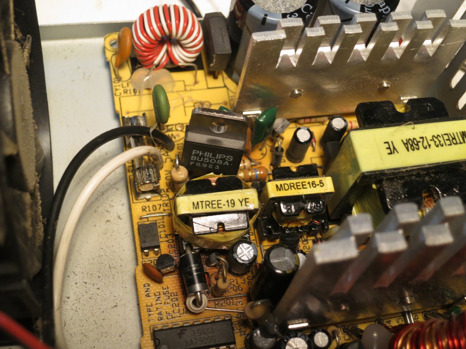
The mains fuse was blown. Not a good sign. There were signs of a struggle, too. Here’s a picture taken after I’d removed a few parts.

Img_7141

There’s an ominous burnt patch on the right of the PCB, and a lightly toasted section below it on the other side of the transformer. These parts all turned out to be part of the standby 5V power supply. If it’s not working, nothing will work, which explains why the PC was dead. The scorched patch was caused by a diode, which fell in to two pieces when I prodded it. The lightly toasted patch was from the switching transistor, which was short-circuit between all pins. The smoothing capacitor on the output of the 5V supply was bulging ominously, though it still seemed to have some capacitance.

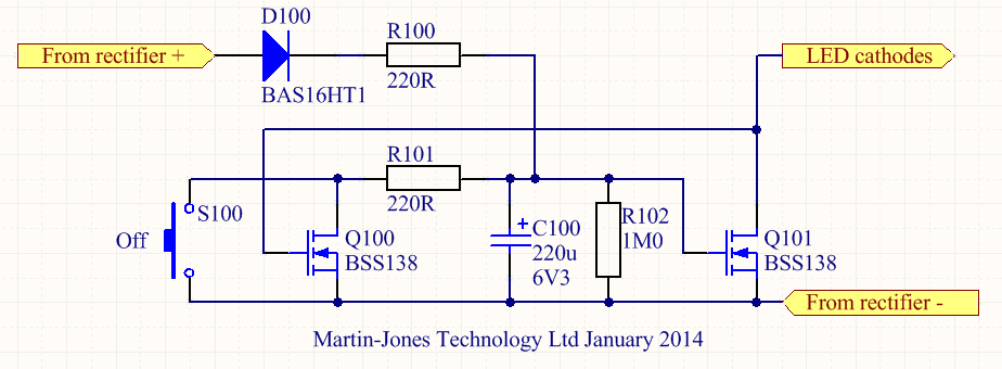
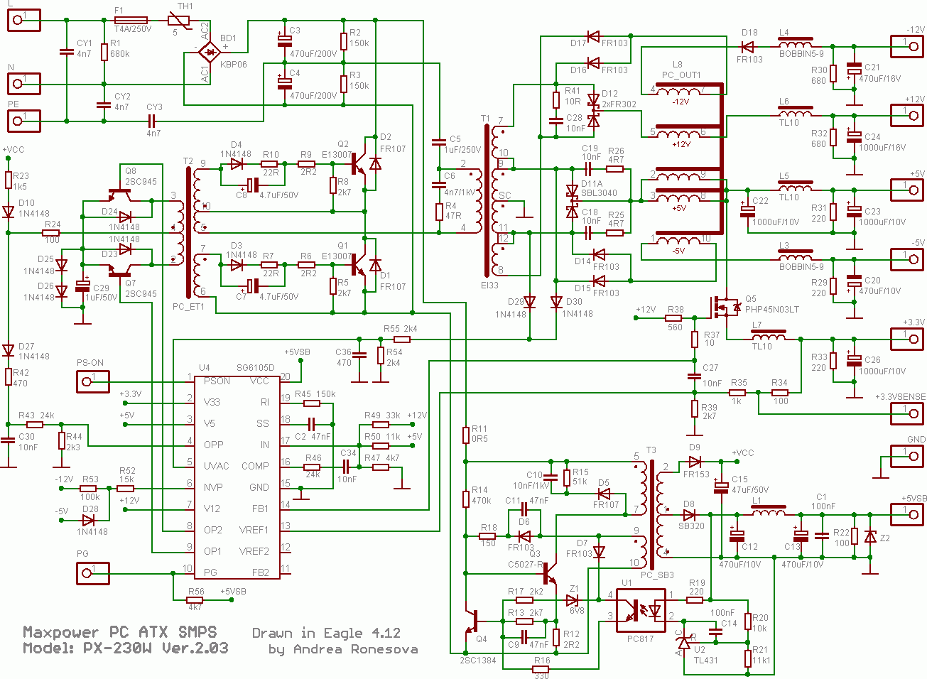
At this point I had a quick web search for likely circuit diagrams of PC power supplies. They’re mostly basically the same, especially at the (ahem) budget end of the market. Here’s the relevant fragment of the circuit diagram of a similar one (original source here from this very handy page of schematics). It’s remarkably similar to the DVD player power supply I wrote about a while ago:

s_atx01aa_section

Component designators I write here will refer to this diagram, not the original PCB. The burnt diode was D8, the short-circuit transistor was Q3, and the bulging capacitor was C12. I replaced all three, using a BU508A for Q3 – rather over-specified, but tough as old boots and I happened to have some. I fitted a new fuse, gingerly switched on and…nothing.

Since Q3 had clearly suffered badly, it would make sense if there was other damage on the primary side of the supply. Semiconductors are always suspect. Probing around, Q4 was dead, short-circuit all ways, and D7 was leaky in both directions. Replace them. I used a BC183 for Q4, with its legs crossed because it has a different pinout. Still nothing. Then I spotted that R12 (3.6 ohms in this power supply) was hanging by one lead because its other lead actually shared a PCB hole with the emitter of Q3! I hadn’t spotted it when replacing Q3. How cheapskate is that? It turned out to be faulty anyway, so I replaced it. By now the board looked a bit crazy with replacement components tacked on the back at all angles.

Img_7140

Switch on…and switch off again quickly! I had a meter connected to the +5V standby output. The meter was set to its 20V range and showed over-range. At least the thing was now working, but it clearly wasn’t regulating. I tried again, bringing it up slowly on the variac. With the mains voltage at about 30V, the output was already at about 6V, but at least it was stable and controllable.

I looked around at the feedback network. U2, a TL431 shunt regulator, was doing sensible things and seemed to be conducting when its input reached 2.5V, as it should. Using my bestest screwdriver to short the output (pins 3 and 4) of the optocoupler U1 should make the power supply think its output is too high and thus drastically reduce the output voltage, but it had hardly any effect. Odd. It turned out that R16 (220R in this unit) was almost open-circuit. Once it was replaced, my screwdriver test worked, but the output still didn’t regulate itself at 5V. This left only one suspect: the optocoupler U1. I scavenged a replacement from another scrap power supply (a cheapo USB phone charger) and fitted it. Success!

IMG_7137

Now the output regulated at exactly 5V, according to the trusty AVO. I did a quick test of the rest of the power supply, pulling the PSON signal to ground. The fan started up and the output voltages were plausible. I decided that was good enough, and tidied up the repair.

Img_7142

Since the diode had clearly had a difficult time, I replaced it with a chunky 3A one (a 1N5420) on ceramic standoffs.

So what had gone wrong? Either the diode and output capacitor had died from a long-term overload (which reminds me, I must check how much current the PC draws from 5V standby) and the rest of the supply had burnt itself to a crisp trying to keep the output up, or the optocoupler had failed so the supply burnt itself and the output diode and capacitor to an even bigger crisp with a huge overvoltage. In the latter case, I’d be worried about the effect on the PC motherboard – the 5V supply could have been well over 5V, which wouldn’t do it any good.

With some trepidation, I reinstalled it in to the PC and switched on. Much to my amazement it worked, so the motherboard hadn’t been fried. Phew. All credit to Asus for an apparently indestructible board – an A7V266. Yes, it’s from 2002. That’s how old the PC is.

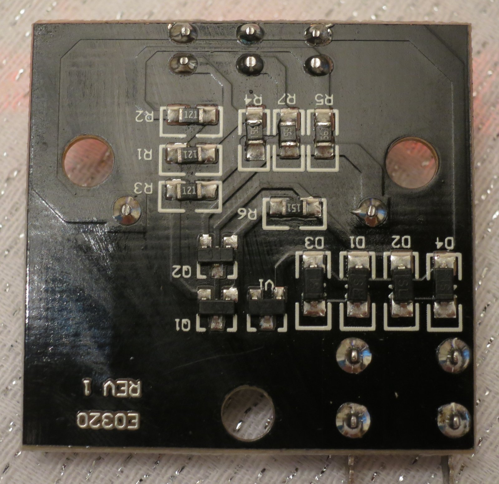
Just for fun, here’s a picture of the collateral damage.

Img_7139

Those nine components were all that was stopping me scanning my document.

Repairing a floppy disc drive

Why on earth would anyone want to repair a floppy disc drive? It’s quite a while since most of us bade them good riddance and started using USB sticks and Flash memory cards. However, I still use floppies from time to time, mostly with my trusty BBC Micro which still sits in the corner of the workshop.

Recently I was asked to recover some documents from some old 5.25″ BBC Micro floppy discs. The documents themselves were in an unusual format, about which more another time, but the first step was to simply get the data off the discs. The discs were 80-track ones, and I have a pair of Chinon FZ-506 80-track drives for the Beeb.

Img_6556

Out of all the various Beeb drives I’ve had over the years, I’ve kept these two because they’re housed in a compact casing with a mains power supply, and they have handy 40/80 track switches on the front, not hidden round the back. One drive has always been a bit reluctant to start spinning, but for occasional workshop use that wasn’t a problem. I’d got in to the habit of just opening and shutting the door a little which would kick the motor into action. However, when it came to intensive use backing up these old discs, which needed both drives, the failure to start became a real pain. I didn’t have a spare drive, and finding another one (especially in Poland) isn’t easy these days.

My curiosity got the better of me and I decided to open up the drive and find out what was wrong with it. It wasn’t hard to take apart and I soon had the motor revealed. Here’s a photo of it sliced into its component parts.

Img_6340

It’s a ‘pancake’ motor, so called because it’s (nearly) flat. The shiny silver bit on the left is the turntable which drives the disc, and it sits in a bearing. The next layer is the circuit board containing the windings and controller circuitry, and below that is the rotor which is a multi-pole magnet on a steel disc.

The motor is controlled by a Mitsubishi M51785P motor controller chip. The chip’s data sheet revealed that the motor has three phases, each of which has a coil to drive the rotor round and a hall effect sensor for feedback. This particular one is arranged with two coils per phase, but occupying 6/7 of a revolution, so the motor goes more slowly than the chip is driving it. At least, I think that’s what’s going on. Here’s a closeup of the circuit board. You can see the six coils, and the coloured wires I soldered on to measure things while the motor was running. Because of the way it’s built, it’s impossible to access most of the circuit board while the motor is assembled.

Img_6338

The controller chip seemed to be doing all the right things: its oscillator was running, and the outputs to the coils were doing sensible things. The coils themselves were all undamaged and measured the same resistance as each other. But I noticed something odd about the hall effect sensors. There are three of them, HG1, HG2 and HG3. I noticed accidentally that if I shorted together the two wires taking the output of HG1 to the controller, the motor still ran but sounded very rough. Not surprising. The same happened if I shorted the output from HG3. But shorting the output from HG2 had no effect at all. Aha! Only HG1 and HG3 seemed to be having any effect on the motor. I swapped HG1 and HG2 just to see what would happen, and the fault moved to HG1. That proved to me that I had a faulty sensor, not a faulty chip.

Where to get a replacement sensor, though? This drive was made some time in the late 1980s, and I couldn’t find hall effect sensors in today’s electronics catalogues which would fit mechanically and electrically. I had a rummage around the workshop and found a scrap 3.5″ floppy drive. A squint at the circuit board revealed a suspiciously hall-effect-looking device of the right shape and size nestled next to the spindle rotor, used for index sensing. Well, it had to be worth a try. I extracted it and fitted it to the 5.25″ drive in place of the faulty one.

Success! The motor now ran more smoothly, and shorting each of the hall sensors in turn had roughly equal effects, so they were now all working. Best of all, the motor started reliably every time. Interestingly it wasn’t as quiet as the other drive, but I suspect the scavenged hall sensor is optimised for magnetic fields from the side rather than the front, given how it was mounted, so it’s probably not perfect.

The last job was to realign the head slightly, because this drive was a bit fussy about reading some discs. I found a disc that it struggled with but that the other drive would read every time, and tweaked the position of the head stepper motor each way a little until this drive read that disc reliably. You can see in this photo that the stepper motor has elongated mounting holes, so it’s possible to loosen its screws (there’s another one just out of shot to the right) and turn the motor a few degrees to adjust the position of the head.

Img_6344

After all this work, the drive read all the discs I asked of it without any problems. I hope it’ll be OK for the next decade or two.

Denon DVD-1720 DVD player power supply schematic and repair

A couple of weeks ago, my wife and I wanted to watch a movie. I went to put the DVD in the player, and was disappointed to find that the machine was dark and didn’t respond to any of its buttons. It was broken.

Img_6385

It’s hard to say that a DVD player is really worth fixing. This one, a Denon DVD-1720, is about 7 years old, and wasn’t expensive when it was new. However, I was curious to know why it had stopped working, and that alone was reason enough to delve inside.

Considering its low cost (I think it cost about £100 when new) it was very neatly constructed. Removing a few screws allows the top to come off (careful of sharp edges) and the plastic front panel just unclips with a bit of gentle persuasion, revealing the guts.

Img_6383

Before we go any further, I have to insert a health warning. Dealing with DVD player power supplies has health risks. There are dangerous voltages present inside. If you don’t have the right equipment or don’t know what you’re doing, you can get a nasty surprise, a terminally broken DVD player, a serious injury or be electrocuted. None of those are fun, especially the one which results in death.

Almost all the electronics are on one big motherboard, apart from a few buttons and lights at the front and the fiddly digital stuff to do with the actual DVD reading, which sits on the green board on pillars in the middle. Undoing the screws from the green board, a few on the motherboard, all the ones on the back of the machine, and unplugging three connectors, makes it possible to wiggle the board free. It’s a bit of a squeeze and the board is fragile, so don’t blame me if you break it.

Img_6380

The power supply is at the rear right corner. Denon have kindly marked in white the area with dangerous voltages in it.

Img_6381

There’s not much to it. It’s clearly a switch-mode flyback converter. The transformer is much too small to be an ordinary mains transformer, and there are no inductors on the secondary side. I did the obvious checks – the fuse wasn’t blown, and the three big pale blue safety resistors measured OK. All the diodes dioded too. Time to put my reverse engineering hat on and dig deeper.

The PCB is nicely marked with the component identifiers on both sides:

Img_6378

so it wasn’t too hard to draw out the circuit diagram.

denon-power-supply-s

It’s a pretty elegant design, using only three transistors. The circuit appears to be a blocking oscillator centred around Q1001 and the transformer. At startup, Q1001 is allowed to conduct, and current starts to flow in the transformer primary. At a certain current, the transformer’s core will saturate so the current can’t increase any more. The voltage induced by the changing core flux in the feedback winding at the bottom of the transformer will suddenly drop, creating a pulse which, fed via C1029 to the gate of Q1001, switches it off. At that point the energy stored in the transformer core has to go somewhere, and it finds its way out through the secondary rectifiers into the outputs. The basic scheme is very similar to the Joule Thief, a simple blocking oscillator for driving LEDs from batteries.

The two transistors Q1003 and Q1008 seem to be involved in regulating the supply. Q1003 can cut off the gate drive to Q1001 in response to three things: the current in R1001 getting too high, the optocoupler IC1001 conducting too much (which indicates that the output voltage is too high) or Q1008 stopping conducting. The latter seems to be a way of shutting down the supply if its output voltages get low, or it might be a cunning standby mechanism involving some more stuff on the secondary side which I haven’t investigated. C1032 seems to be there to make sure that the power supply starts up.

I powered the bare motherboard from an isolating transformer (don’t try this at home, folks, unless you know what one of those is and how to use it) and measured some things. There was precisely no activity going on at all, apart from 300V on the reservoir capacitor C1004 and Q1001’s drain, as expected. I first laid the blame on the little electrolytic C1032, since they’re the most unreliable components in any modern electronics, but tacking another 10uF across it didn’t help. Holding my breath and briefly shorting C1032 didn’t bring anything to life, either.

Then I measured some of the DC conditions. Everything around Q1008 was OK, with R1096 and R1034 merrily feeding electrons into Q1003’s base and keeping Q1001 switched off. High-value resistors are the next most suspicious components in a circuit like this, especially when they’re teeny-tiny ones. I checked around the 1.8 megohm R1005 and R1006 which pull up Q1001’s gate. Clearly it couldn’t work without them. Lo and behold, my 10 megohm input meter showed 250V at the junction of R1005 and R1006. That can’t be right – the voltage should be more like 150V, since the resistors are the same value and basically connected straight across the 300V supply. I pulled R1006 out of its hiding place and measured it – it was open-circuit. Gotcha!

Soldering in a replacement 1.8 megohm resistor for R1006 brought the whole thing back to life. The secondaries seemed to have sensible voltages on them (3.3V and 12V at a glance) so I reassembled it far enough to test. It lit up, accepted a disk and played it. Success!

It’s a credit to Denon’s neat design that there were no screws left over when I put it back together. The whole machine is now back in action for the sake of a 2p resistor.

Tapping a hole without a tap

No, this is nothing to do with plumbing. It’s much drier than that.

Today I wanted to screw some resistors to a heatsink. The resistors have 2.5mm mounting holes, so I looked in the M2.5 fasteners drawer and found plenty of screws but no nuts. That’s not going to work. And I haven’t got any self-tapping screws that small, and self-tapping screws are a bit horrid anyway. Unless…I could tap the holes in my heatsink so the screws would screw directly into them. That would be easy if I had an M2.5 tap, but I don’t. Only 6BA, M3, M4, M5, M6, M10x1.0 and 1/4″ UNF, since you ask.

What to do? Well, the heatsink is aluminium, so fairly soft. And the screws are steel, so harder. I decided to try making a tap out of a screw. I attacked one with a cutting disc on a Dremel, like this:

Img_6367If you try this at home, keep your fingers out of the way. Oh, and switch the Dremel on. It works better like that. The result was a screw with a couple of flutes in the end of the thread:

Img_6366

I took the photo after the screw had been used to tap half a dozen holes, so it’s a bit mangled, but you get the idea.

Just use the screw like a tap, turning it gently into the hole, reversing every now and again to break the swarf. It worked a treat, and all six of my holes take M2.5 screws very neatly. If only they lined up with the holes in the resistors. Sigh.

Action shot of tapping in progress. You can see the sharp edge of the flute which helps to cut the thread, and the authentically-mangled head of the screw.

Img_6375

Herrmans H-Track Standlight Modification

In a previous article, I took apart a Herrmans H-Track dynamo rear light. I wasn’t happy with how the standlight behaved: it stayed on for a very long time. Even after an hour, some glow was still visible. This is more irritating than helpful because it attracts attention to the bike when it’s parked, and many times has caused people to helpfully call, “You’ve left your light on” to me when I’ve locked up my bike.

I also saw recently a poster at a railway station telling cyclists, in no uncertain terms, to switch off their lights when wheeling their bikes on station platforms – apparently there’s a real risk of causing trouble. Train drivers are highly attuned to spotting red lights, and so having extra ones on wayward bicycles is a safety problem.

For these reasons I wanted to get some sort of control over the standlight. The German StVZO regulations (section 67, Technische Anforderung 4) say that the standlight should stay on for at least 4 minutes, so I made that my target. Most such problems these days seem to get solved with an Arduino, but that’s really boring. I wanted to do it the old-fashioned analogue way. After a bit of playing around, I came up with a little circuit which automatically switches off the standlight after 4-6 minutes, and also has a button to switch it off manually. It only uses seven components. Here’s the schematic diagram.

Offer_schematic

It’s a simple monostable multivibrator made of two transistors. When the dynamo is generating power, capacitor C100 charges up via resistor R100 and diode D100. It only charges to about 5V because there’s a 5V-ish zener diode in the main light. The voltage on C100, and thus Q101’s gate, keeps Q101 switched on so the LEDs light up. Because Q101 is conducting, there’s very little voltage on its drain, so Q100 is switched off. Meanwhile, in the original electronics of the light, the standlight capacitor is charging up so that the LEDs still get a power supply when the dynamo stops.

When the dynamo does stop generating, C100 no longer receives any charge but instead starts discharging through R102. Because C100 and R102 are both large, and Q101’s gate has a very high resistance, this takes several minutes. But eventually the voltage on C100 drops low enough (about 1.5V) so that Q101 starts to turn off. As it does so, the voltage on Q101’s drain starts to increase, which gradually switches Q100 on. Once Q100 starts conducting, C100 also discharges through R101, so the whole process accelerates. Q100 and Q101 thus form a sort of Schmitt trigger, which switches off Q101, and therefore the LEDs, fairly quickly at the end of a timing period of a few minutes.

The button S100 is there so that it’s possible to manually discharge C100 and switch the light off, for example when parking the bike. Note that this doesn’t discharge the standlight capacitor so, next time the bike starts moving, the standlight will already be at least partially charged. This is handy.

None of the components are critical. D100 can be any small-signal silicon diode, and Q100/Q101 are just logic-level N-channel MOSFETs.

I built the circuit on a little piece of matrix board. It fitted easily into spare space in the light.IMG_6309

Here are the connections to the original light PCB. The green wire goes to the LED cathodes. You can make out where I’ve rather untidily cut the original PCB track to the LED cathodes. I had to cut it in two places because it was used as a ‘through route’ from the rectifiers to the rest of the electronics. The resulting gap is bridged by the bit of white mod wire soldered to D3.

IMG_6308Fitting in the button, S100, was a bit more tricky. I ended up using a miniature PCB-mounting button and gluing it in into the back of the case using epoxy resin. The button protrudes through a little hole but is doesn’t stick out. I’m hoping that will protect it from damage but still make it easy to use.

IMG_6264

The brown button is visible at the top left of this photo. When the light is mounted on the bike, it’s still accessible.IMG_6310I’ve been using the modified light for a few days now and I’m pleased with it. The light itself is very bright, so being able to switch it off when I stop to buy bread is properly handy.

NAT loopback and local DNS again

A while ago I had to do some fiddling to make my internet-accessible server also work from behind the Orange Livebox router at home. I described the problem and first fix in this post. Yesterday, it all stopped working, which was very annoying. It was my fault.

What was the problem? Well, the dynamic DNS entry was no longer updating, so when the IP address of the home router changed, as it does from time to time, the outside world could no longer find my server. It turns out that the little script which keeps the dynamic DNS updated relies on being able to find two addresses on the internet which are in the same domain as my dynamic address. For the sake of this example, we’re using ‘example.dyn.com’ as my dynamic IP address. The dynamic DNS update process also needs to be able to find ‘echo.dyn.com’ (which finds out the IP address of my router) and ‘rh.dyn.com’ (which accepts the update itself). I’d got my local DNS set up to override the whole ‘dyn.com’ domain so the update process simply wasn’t working – it could find neither ‘echo.dyn.com’ or ‘rh.dyn.com’.

The fix was delightfully simple. I just changed my DNS setup so it overrode only the specific address I was interested in. So now /etc/bind/named.conf.local has the following section in:

zone "example.dyn.com" {
  type master;
  file "/etc/bind/db.example.dyn.com";
};

and the zone file /etc/bind/db.example.dyn.com looks like:

$ORIGIN .
$TTL 604800 ; 1 week
example.dyn.com IN SOA localhost. root.localhost. (
  2009060801 ; serial
  604800 ; refresh (1 week)
  86400 ; retry (1 day)
  2419200 ; expire (4 weeks)
  604800 ; minimum (1 week)
  )
  NS sheevaplug
  A 192.168.1.10

Problem solved – the dynamic DNS update works and my server is visible from the internet again. Now I can go to the office and use it.

Herrmans H-Track rear light teardown and schematic

I’m in the process of fitting dynamo lights to my wife’s bike and to mine. For our rear lights, I chose a light I hadn’t seen before: the Herrmans H-Track. It’s relatively cheap but seems to have good reviews. It meets all the relevant standards, if you care about that sort of thing. A quick test on the bench showed that it was nice and bright, and the illuminated ring round the outside is eye-catching.

Img_6207

The standlight works quite well but stays lit for a long time (around 15 minutes, I’d estimate), gradually dimming until it gives up. That’s not as nice as the B+M DTopLight I have on another bike, which stays lit for the requisite four minutes then switches off. I was curious to see if it was possible to improve it, so I took it apart.

The light is glued together but there are little gaps between the two halves at the bottom, which make it relatively easy to lever apart without damaging it. Here’s what’s inside.

Img_6208

A little PCB with not much visible – three LEDs and a capacitor. It’s nicely made, with a fibreglass PCB, but there’s no waterproofing or other sealing. The rest of the components are surface-mounted on the other side of the board. I noted in passing that neither of the wires is connected to the mounting screws, which is handy for lighting systems like the Solidlights 1203DR which need both wires to the rear light to be isolated from the frame. Here’s a closeup of the PCB.

Img_6210

Not a lot to it, really. You get what you pay for. For the curious, here’s the circuit diagram I traced out. It’s clear that the H-Track doesn’t have any protection against overvoltage, so you’re in trouble if your front light comes disconnected.

taillight

What about improving the standlight behaviour? Well, I’ve worked out a modification for that but haven’t tried it out in a real light yet. Watch this space.