Tag Archives: electronics

Bubble Development Board Ethernet and SD working

I’ve got a couple more features of the Bubble development board working. The Micro SD card needed pullup resistors from its data and command/data lines, then it Just Worked though the card detect function doesn’t do anything yet. While modifying the VHDL to get Ethernet working (see below) I noticed a message that sd_card_detect has been optimised out of the design because it’s not connected to anything. That would explain it. I’ll look at it in a while. I’m not even sure whether the kernel driver supports a card detect line.

Most excitingly, Ethernet works now. I’ve connected its interrupt output to a register in the CPLD and modified the platform code in the kernel to point it at the relevant interrupt, and it works! It gets an address by DHCP and I’ve successfully copied files to and from it by scp. It seems a bit slow, topping out at about 3.5Mbit/s, but the Samosa bus timing is pretty relaxed and could probably be speeded up significantly. I saw one transmit timeout message, too, so maybe something isn’t quite right yet. Oh, and the MDI/MDI-X negotiation still seems a bit unhappy so the link doesn’t come up every time.

I’d also like to wire the ‘link’ output of the W5100 to a GPIO so that the driver can see it and do sensible things when the cable gets plugged in and unplugged.

Raspberry Pi Power Architecture

Embarking on some work with the Raspberry Pi recently, I wanted to know what its power architecture looked like. The schematic diagrams are freely available but a quick web search didn’t reveal any higher-level design documents like this, so I drew my own and here it is.

I offer no guarantees of accuracy. Don’t blame me if you use this documentation and destroy your Raspberry Pi or anything else. This is not an official document. I hope it’s useful to someone.

The original version of this that I posted in April 2013 had a mistake in it, which Kai kindly pointed out. The version below has been corrected.

Raspberry Pi Power Architecture2

There’s a nice shiny pdf of it here: Raspberry Pi Power Architecture

Bubble Development Board – progress

Having now had the Bubble Development Boards for a few days, I’ve tested a few more features.

Both JTAG sockets (Xilinx 14-pin and ARM 20-pin) work with their respective dongles.

The Ethernet adapter, a Wiznet W5100, is showing signs of life. If I plug an Ethernet cable into it, the ‘link’, ‘full duplex’ and speed indicator LEDs come on. Frequently the ‘link’ LED blinks continuously along with the Rx LED. I don’t know why, though searching on the web indicates that the W5100 can be fussy about the choice of transformer it’s used with, and sometimes about what kind of hub it’s plugged into – apparenly the automatic MDI/MDI-X negotiation can get confused. The tests were done with a TP-Link TL-SF1005D switch and I haven’t tried any other. Sometimes, though, the link will settle down to a steady state, then I see the Tx and Rx LEDs doing sensible things.

DSC_0453

The W5100 chip is wired to the Samosa bus with very simple address decoding so that it should appear every 4 bytes across the whole 256-byte Samosa address range. Manually poking and peeking its registers from the Bubble board’s boot loader gave sensible results, and I even managed to get it to try and send a packet, the Tx LED blinking reassuringly.

Recent Linux kernels have a driver for the W5100. I tried kernel version 3.7.1 which has already been patched for the Bubble board. The existing drivers expect the chip to be I/O or memory mapped, which is not the case on this board because it’s on the Samosa bus. The Samosa bus is accessed using its own function calls inside the kernel. I patched the driver, and had to undo one or two assumptions made in the code about memory access, and the results are promising: the chip is found correctly, interface eth0 appears, and it even sends packets from the DHCP client attempting to get itself an address. However, the first attempt to send a packet results in an error:

NETDEV WATCHDOG: eth0 (w5100): transmit queue 0 timed out

and a stack trace, though the kernel carries on running. It seems that the Ethernet chip’s interrupts are not making it into the kernel. This turns out to be due to the offending interrupt line not being connected to anything in the Bubble board’s CPLD, so I’ll have to fix that next. That needs the Xilinx programming dongle which I haven’t got with me at the moment.

Bubble Development Board – first prototypes received

A couple of days ago I received the first examples of the Bubble Development Board and started testing them.

DSC_0420

Much to my joy, the board fits neatly into a low-cost plastic case from Farnell, part number 1526699. With front and rear panels suitably cut out, it should be well protected and easy to connect things to.

DSC_0421

But does it work? Well, yes, largely. Here are the results so far.

  • Power: the LEDs (green for +5V input, orange for VDD_IO from the Bubble) come on and the Bubble board starts up reliably.
  • Reset button: does what it says on the tin.
  • Serial port: console works.
  • USB host: tested to work with a memory stick and a USB-to-Ethernet adapter.
  • USB slave: working. USB networking connection successfully established to a desktop PC as documented at http://www.balloonboard.org/balloonwiki/USBNetworking.
  • Audio: output works, straight into a pair of headphones, and quality seems good with no unpleasant background noises. Haven’t tried input yet.
  • HDMI: the Bubble board I was using was set up to drive an LCD panel, but by installing fbset and fiddling around with the settings (making them roughly 800×600, 60Hz) I managed to get a display on a monitor connected to the HDMI port. However, the image tends to disappear every few seconds and then come back again with some flickering, so something’s not quite right. I tried another monitor via an HDMI-DVI cable with the same result.
  • Micro SD socket: not working yet. The kernel reports an error during boot and /dev/mmc* devices don’t appear. I’ve noticed that other implementations of the SD card socket from Bubble have pullup resistors on all the data and clock lines which I neglected to put on this board. This might be an easy fix because the wiring looks right.
  • JTAG, Samosa, Raspberry Pi header, Ethernet: not tested yet.

Here’s another picture with the Bubble board turned over so you can see what’s on it.

DSC_0422

HP 16534A triggering problems

DSC_0404

One of my HP 16500B logic analysis systems has a 16534A digital oscilloscope module installed. The module has a great specification: two channels, 2Gsamples/sec, 500MHz analogue bandwidth, and 32k record length. I would find it a really useful debugging tool, if it worked properly. Sadly it doesn’t.

Though it displays a trace successfully, and the controls work, it won’t trigger. The only way I get a trace is by auto-trigger. In this case the trace isn’t synchronised, so it’s impossible to catch a particular event at a particular time. Here it is displaying a square wave (well, it’s nearly square – I hadn’t adjusted the probe compensation so it’s a bit curvy on the top and bottom). Adjusting the trigger level just doesn’t make any difference.

DSC_0409

The service manual for the 16534A isn’t very helpful. It describes roughly what the self-tests do, and how to run the self-calibration procedure, but has no detailed circuit information. The self-test reports a ‘D/A’ failure:

DSC_0405and the self-calibration procedure fails on the Trigger and Hysteresis sections:

DSC_0406

The service guide describes the D/A test like this:

Test DAC This test verifies the correct operation of the D/A convertor on the board.
Both the offset and trigger level D/A convertors for each channel are set to a reference
level and then changed. The logic trigger IC is programmed to detect the changes. The
detection of a correct trigger indicates that the D/A convertor is operating normally.

It seems clear that the offset D/A converter is working, since the offset control works and moves the trace up and down as it should. However, the trigger level control doesn’t seem to be doing what it should. I had a look at the board, looking for components likely to be the DAC or trigger IC. Unfortunately, the semiconductors on there seem to be mostly either standard ECL logic, trivial things like op-amps, or magic custom HP chips with dozens of pins. One exception was this:

DSC_0410

It’s an AD96687 from Analog Devices, which is a dual high-speed comparator with ECL outputs. If I was designing a high-speed trigger circuit using 1994-vintage components, I might use a device like this. I’ve had a look at all its pins with the power switched on and a signal applied and tests running, and none of them seem to change at all. One noninverting input is stuck at +5V, and the other inputs are near ground. One set of outputs isn’t even showing valid ECL logic levels, but it may be unused and thus have no load resistors on it.

Maybe it’s a red herring and nothing to do with the triggering at all, but I’m suspicious that I never see anything change. Without more circuit information, it’s hard to get much further, sadly.


How to Get a Real Serial Port – PCI Express under Linux

serialport

I do a lot of hardware and software development on things with embedded processors, ranging from little 8-bit Atmel chips to big 32-bit ARM-based things like the Balloon Board. Often the systems they’re built in to don’t have much of a display or keyboard, so getting information in and out of them for testing and debugging purposes is tricky. One thing that really helps is a good old-fashioned serial port. Pretty much every embedded processor has some kind of serial port on it, and they’re generally very easy to use from software so can be got working very early in the development process.

In order to make use of a serial port, you need another one to connect it to. This used to be easy: they used to be ubiquitous on desktop and laptop PCs. However, in the last 10 years they’ve gradually died out and been replaced by USB to serial adapters. Though such adapters are cheap and readily available, I’ve had loads of problems with them. Since they’re easily detached, they often seem to go missing, or get left in toolboxes and attached to projects. Some of the ones I’ve used also sometimes seem to get themselves in a mess and start turning my data into junk until they’re unplugged and reinserted. This is not helpful.

usb-serial

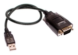
It can also be hard to predict how the serial port will be identified when it’s plugged in: under Windows, it gets a COM port number, but which number it gets depends on how many other such devices have ever been plugged into that machine and even into which USB socket, so setting debugging software up to find the one you want is impossible. Under Linux the same problem exists but with an extra feature: if you have a terminal program watching a serial port, then accidentally unplug it and plug it back in again, the program carries on as if nothing has happened but you don’t see any output . That’s because the operating system thinks that the old port is still in use even though it’s not there any more, and allocates a new, available number when it’s plugged back in, so /dev/ttyUSB0 magically becomes /dev/ttyUSB1. Even restarting your terminal program doesn’t work, because it’s still going to look at the old number. You can reconfigure the terminal program to look at the new one, but then you’ll find that if you shut everything down and restart it, the USB serial port will have moved back to /dev/ttyUSB0. The only way out is to stop the program, unplug the adapter again, plug it back in and restart the program. This is a serious pain.

I recently had the chance to do something about this problem in my own workshop. I was configuring a new Linux PC for the workbench, and discovered, to my great joy, a little-documented feature on the shiny new Gigabyte GA-Z77N-WIFI motherboard: a serial port! Tucked away on a little white connector, there it was, forgotten and unloved. All it needed was a cable to bring it to the outside world, and it worked. It turns up as COM1 under Windows and /dev/ttyS0 under Linux, and it’s always there, can’t be unplugged, and never changes its number. Wonderful.

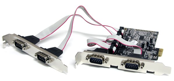
If one serial port is good, more must be better. The motherboard has a PCI Express slot on it, intended for a turbo-nutter graphics card which this machine didn’t need. I found a PCI Express serial port card, similar to the PEX4S553 from Startech.com which looked like it would do the trick. Actually I had it lying around because I’d fitted it to a Mac Pro a couple of years ago, but it never worked properly in the Mac.

startech-card

I put it in the machine and switched on. Would it work? Typing lspci revealed that it was there, and was working, so were the ports usable?

ls /dev/ttyS*
ttyS0    ttyS1    ttyS2    ttyS3

Not bad, but why only four? There’s the one on the motherboard, plus four on the card, so that should be five, right? Well, to cut a long story short, after a bit of web research, I found that the standard serial port driver in the Linux kernel only looks for four serial ports as standard, but responds to a kernel command line parameter to make it look for more (or indeed less). Experimentally rebooting and manually editing the kernel command line in grub to add

8250.nr_uarts=5

to the end of it worked! I had all five ports, and they all did what they should. To make the change permanent, I edited /etc/default/grub to add 8250.nr_uarts=5 to the end of the GRUB_CMDLINE_LINUX_DEFAULT parameter, and ran update-grub. Now all five ports turn up every time I switch the machine on, and I’m a happy developer. By the way, I’m running Debian Linux 6.0 (squeezy) with kernel version 3.2.something from backports, but the kernel version won’t make any difference – this stuff is all ancient history.

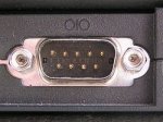
It remained only to tidy up the wiring. The ports on the Startech card appear on 10-pin headers. The wiring on these is simple: pin 1 on the header goes to pin 1 on the 9-pin D connector, pin 2 to pin 2, and so on. Pin 10 isn’t used. However, the way the pins are numbered differs between the headers and the D connectors: the headers are numbered on alternate sides, like a street, so one side is 1/3/5/7/9 and the other is 2/4/6/8/10. The D connectors are numbered 1-5 on the top row and 6-9 on the bottom row.

I had a load of serial port breakout cables in the bottom of my PC parts box, left over from the early 90s. I found that many of them were wired straight-through, like this:

DSC_0359[1]

which is wrong for the Startech card. I had to rewire them to look like this:
:DSC_0362[1] DSC_0361[1]

according to the correct pin numbering, and then they worked. The card fitted neatly in the back of the machine:

DSC_0366[1]and, as a finishing touch, I did a ‘case mod’ to mount two of the serial ports on the unused 3.5″ floppy drive blanking plate:

DSC_0365[1]Notice how they’re labelled, so I always know which is which! It’s a very practical arrangement for the workbench, having reliable serial ports always at hand. The other two are round the back, and will probably be used less frequently.

Motorboating in Space

zaxxon3

Or, how to stop Zaxxon going thump-thump-thump.

‘Motorboating’ has been a problem in electronics almost as long as electronics has existed. It gets its name from a characteristic thumping or buzzing noise, reminiscent of a motor boat’s engine. It’s a problem which usually occurs in audio amplifiers, and it happens either because of a design error or faulty components. Sometimes a change in an amplifier’s operating environment, such as a radio battery running down, can cause it. It’s loud, annoying, and can even damage speakers,

The reason for the noise is feedback. If an amplifier drives a signal into a loudspeaker, the power for that signal has to come from its power supply. Its power supply, especially if it’s a run-down radio battery, isn’t perfect. Drawing power from it makes its output drop in voltage for a moment. Unfortunately, electronic circuits aren’t perfect either. Their behaviour is strongly affected by their power supply. Connect such a circuit to such a power supply and amplifier, and you have a vicious circle: circuit sends a signal to amplifier, amplifier sends it to speaker and draws more power, power supply affects circuit, which makes another signal which gets sent to amplifier, and so on. It’s called feedback because the output signal feeds back into the input, via an unorthodox route. The circle of feedback can lead to the regular buzzing noise – the motorboating.

Recently I have restored a Zaxxon arcade game circuit board, which dates from 1982 (actually, it’s a bootleg, but the circuit is largely the same). I got it working well, but with one big problem: the sound was accompanied by a constant thumping noise which wasn’t supposed to be there. Here’s a short movie of how it sounded. It’s especially noticeable at the start and end of the clip.

Fans of the game will know that Zaxxon has very distinctive sound. Many video games at the time used digital techniques, often using standard chips, to generate their sound, which gives them a characteristic bleepy quality. Zaxxon is different. It uses what amounts to an analogue synthesizer: a magnificent assembly of timers, oscillators, amplifiers and filters. It has a lot in common with the kind of instruments used in pop music at the time. It makes a glorious, raucous noise.

IMG_3560

But this kind of analogue circuitry has a problem, especially when it’s cheaply built using early 1980s technology: it’s very sensitive to its power supply. Any variation in the power supply basically gets straight to the synthesizer’s output. What’s more, Zaxxon’s loudspeaker amplifier runs from the same power supply as the synthesizer. This lot is a recipe for motorboating, and that’s exactly what happened to my game.

zaxxon-power-1

Of course, we have to assume that it all worked properly when it came out of the factory, but then it would have been running from an official Zaxxon power supply. The one I use in my arcade game test rig may not be as good as the original one, but it’s good enough for most things, and I wasn’t going to change it just to fix this problem. So I had to come up with a modification to keep apart the amplifier power and the synthesizer power.

The traditional cheap and cheerful way of keeping power supplies apart, known as decoupling them, is simply to put a resistor and capacitor between them, like this:

DSC_0335

This decoupling means that variations in one power supply have a smaller effect on the other. It works well, and has been used in millions of electronic devices from the earliest days of radio. However, a certain amount of power is always lost in the resistor. Many circuits don’t mind this, or can be designed to handle it. I tried this approach with Zaxxon,and it turned out that the sound synthesizer doesn’t cope well with a reduced supply voltage. Many of the effects, especially explosions, became disappointingly quiet. I had to find another way.

Arcade games typically use two power supplies: 5 volts for their digital circuits, and 12 volts for the sound amplifier. This gave me an idea: how about using the 5 volt supply to run the audio synthesizer, keeping it neatly separate from the amplifier? Clearly the synthesizer wouldn’t just work from 5 volts: I’d already had trouble with it running from about 10 volts in the decoupling experiment. However, there was a solution. It would be possible to boost the 5 volt power supply up to 12 volts using, aptly, a boost converter. Boost converter modules are cheap and readily available thanks to low-cost far eastern manufacturing. The one I chose had a conveniently adjustable output voltage. It didn’t take long to wire it up. I’d already separated the amplifier supply from the synthesizer, and so I just had to take a wire from the existing 5 volt supply to the sound board, check my work and switch on.

zaxxon-power-2

It worked! The sound was now perfect, with no strange thumping effects, and everything seemed to be at the right volume. It remained only to make the modification more solid, and there was even a handy spare hole  to mount the boost converter in. Job done!

wpid-DSC_0326.jpg

Henelec PA25 power amplifier and MU442 power supply

Over on the Vintage Radio Forum, someone asked recently about the Henelec PA25 power amplifier module. The PA25 was produced by Henry’s Radio of London in around 1970. Since I have a pair of them, including the associated MU442 power unit, I’ve documented them here.

Here are a couple of general views. The MU442 has sockets for mains in, signal input (3-pin DIN) and speaker outputs (DIN again). There are also a pair of power supply fuses. Connections to the PA25 modules are via wiring harnesses with edge connectors.

Img_3997

IMG_3999


Here’s what one of the modules looks like. It’s a sandwich of a PCB and heatsink.


IMG_4000


This is what’s on the PCB…


IMG_4003

…and on the heatsink…

IMG_4004


…and the back of the PCB.

IMG_4001


The heatsink has a pretty label on it:

Img_4005


This is the MU442.

Img_4006


Inside, there’s a mains transformer with 2x 22VAC secondary windings, four BYZ13N rectifier diodes in stud-mounted packages, and a pair of smoothing capacitors.

Img_4007


I drew out the schematic diagram of the circuit. It’s made with silicon transistors and is pretty conventional, I think,

PA25_Schematic


Here’s a PDF file of it: PA25_Schematic


150W Boost Converter Schematic

In a recent project, I needed a boost converter to step up 5V to about 8V at a few amps. A few different Chinese-made boost converter modules are available from various sources: I’ve seen them on eBay and Amazon. One very common one is known as the ‘150W Boost Converter’. I believe it’s intended for charging laptops from car batteries. It’s specified to take an input of 10-32V and output 12-35V, which isn’t quite what I was looking for, but the price was right so I thought I’d take a chance. This is what I found.

boost

I had a good look at the circuit board. It’s based on the UC3843 chip, which is a pretty old device (I think it dates back to 1984) and is often found in PC power supplies. However, its age and ubiquity means that documentation on it is readily available. I traced out the circuit, so here’s the schematic diagram:

150W_ boost

You can also have it as a PDF file: 150W_ boost.

It’s a pretty straightforward boost converter topology with a MOSFET switching transistor and a variable resistor in the feedback loop to set the output voltage. There is no over-current, over-voltage or reverse polarity protection at all, and the chip isn’t designed for low power consumption so this module wouldn’t be suitable where very low standby power is a requirement. There are a couple of interesting features, though.

The circuit includes an arrangement with an NPN transistor which feeds some bias to the current sense feedback loop. According to the UC3843 datasheet, this improves the stability of the converter at duty cycles higher than 50%.

The control supply for the UC3843 is derived from a 9V regulator, so it’s independent of the input or output voltage. This is convenient.

The UC3843 is designed to operate from fairly high supply voltages, and won’t start up until its supply voltage reaches 8.4V. That was a bit of a problem for my application, where the input voltage was only 5V. However, there’s nothing to say that the chip power supply has to be the same as the power input. In fact, the module already has a handy 9V regulator which feeds the control chip. Looking at the circuit diagram, there are even a pair of resistors (I’ve labelled them R1 and R2) which select whether that regulator is fed from the input or the output. As supplied, R2 was fitted, so the control chip was fed from the output. Here’s a closeup of the relevant part of the board showing R1 and R2.

DSC_0310crop

My application happened to have a low-current 12V supply available, which would be perfect for powering the UC3843. I simply removed R2 and connected my 12V supply to the point where the black arrow is in the photograph. The boost converter now worked perfectly with a 5V input.

I also had to modify it a little to be able to reduce the output voltage below about 11V. R3, labelled in the photo, is part of the feedback network. I simply removed it and replaced it with a piece of wire. Now the output voltage was variable down to 5V, and I was able to set it to the 8V I wanted.

The module seemed very comfortable delivering 3.3A at around 8V, and drew about 5A from the the 5V input. The heatsinks only got slightly warm.

Unfortunately, the power supply I wanted to run the converter and its load from didn’t like starting up with it all connected. This is quite often a problem with boost converters, since the inrush current at startup can be very large as the controller tries to bring the output up to voltage as quickly as possible. I solved this by adding a soft-start circuit to the module. More on that later.

Espial Arcade Game Pinout

espial

Getting through my collection of not-quite-working arcade PCBs, I’ve just sorted out ‘Espial‘ and made a JAMMA adapter for it. In the process, I discovered something missing from the available pinouts of this game online. In the game you have two weapons: you can drop bombs on ground targets, and fire lasers at flying targets. In MAME, the game uses two separate fire buttons, one for each weapon. However, the published PCB pinouts only show one fire button connection for each player. There’s a DIP switch setting which combines both bombs and lasers on to one fire button, which worked for me, but that’s not the same as having separate control of the weapons.

IMG_3734

I set about looking for the second fire button connections. The MAME source code shows that the second fire button for player 1 is in bit 6 of the port at 0x6081, the same port as some of the DIP switches. The inputs all seem to be handled by 74LS368 buffers. Prodding their inputs with a grounded bit of wire during a game revealed that the second fire button for player 1 was on pin 14 of IC2F. Aha! It does exist. Tracing the PCB tracks led me to pin E on the underside of the edge connector via R17. A similar process led me to pin G for the second fire button for player 2.

Here’s my updated version of the pinout diagram:

              COMPONENT  |  SOLDER
    ---------------------+----------------------
               GND   | 1 | A |   GND 
               GND   | 2 | B |   GND
                     | 3 | C |   
               +5V   | 4 | D |   +5V
                     | 5 | E |   1P.Laser
      Coin Counter   | 6 | F |   
           2P.Down   | 7 | G |   2P.Laser
              Coin   | 8 | H |   
           1P.Bomb   | 9 | I |   Service
          1P.Start   |10 | J |   2P.Start
           1P.Left   |11 | K |   1P.Right
             1P.Up   |12 | L |   2P.Up
           2P.Left   |13 | M |   2P.Right
           2P.Bomb   |14 | N |   1P.Down
               GND   |15 | O |   GND
               Red   |16 | P |   Green
              Blue   |17 | Q |   Sync
                     |18 | R |   Speaker
                     |19 | S |   
              +12V   |20 | T |   +12V
               GND   |21 | U |   GND
               GND   |22 | V |   GND

I also found that it was important to connect up all the power and ground connections, even the seemingly duplicated ones, before the game would start up correctly. But start up it does, and it’s fun. I hope this information is useful to someone.

Img_3737